J!m
Veteran and General Yakker
Soldering in a chem lab is probably sub-optimal as well...
Hi DougHey Guys,
When I started this adventure, I was to post plenty of pictures and ask any questions when unsure. I've asked honest questions, Wanting to know if what I've done so far was the correct way, and I've gotten little or no answers. I apologize if I came across as a know-it-all in a previous post. I didn't mean to because I don't. I was trying to add a little humor. So, I'm asking again. Is there anything in the work I've completed on the Control Board or the Backplanes that needs correcting? Before I move on. I want to do things the right way. If anyone would still like to lead in the right direction, I would greatly appreciate the help. Thank You
Doug


Hexis22, that's some NASA level soldering there!Doug,
First, thank you for posting your build pictures, it's always interesting reviewing other peoples experience building these projects. Having said that, my day job has been crazy busy and I have not had the chance to post on this forum lately.
Overall your progress looks very good and I do not see anything requiring immediate correction before proceeding.
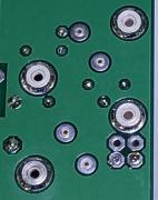
The only feedback I have relates to the PEM nut soldering. It's difficult to accurately evaluate the solder joints with shadows and reflections on your somewhat low resolution pictures, however see below for examples of a few I would touch up with a hot iron and liquid flux. The edges appear rough and jagged. See second picture for example of what you should shoot for in solder quantity and appearance.
View attachment 86684

View attachment 86685
You tend to get the hang of it after your first 30-40 backplane boards…Hexis22, that's some NASA level soldering there!
You tend to get the hang of it after your first 30-40 backplane boards…
Hi Doug
This group is not bashful and would have criticized if it was due. So far your work looks very good. Nice solder joints and nice clean board after the soldering job.
Doug,
First, thank you for posting your build pictures, it's always interesting reviewing other peoples experience building these projects. Having said that, my day job has been crazy busy and I have not had the chance to post on this forum lately.
Overall your progress looks very good and I do not see anything requiring immediate correction before proceeding.
The only feedback I have relates to the PEM nut soldering. It's difficult to accurately evaluate the solder joints with shadows and reflections on your somewhat low resolution pictures, however see below for examples of a few I would touch up with a hot iron and liquid flux. The edges appear rough and jagged. See second picture for example of what you should shoot for in solder quantity and appearance.
View attachment 86684

View attachment 86685
Doug, I've read the whole thread over and your prose is very non-confrontational. Nothing to worry about there.
And believe me, WE ALL understand the anticipation and building excitement, and that creeps into your posts...and that's a good thing, if it wasn't you're a BOT!!
A few comments:Hey Guys, its been a few days since I posted any pictures of my progress. Taking my time and doing a lot of reading on the assembly procedures. I got the Backplanes wired up and started assembly of the new chassis. Working on the Transformer getting it ready.
Thanks for looking.....
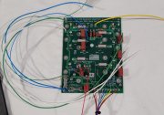
Left
View attachment 86741
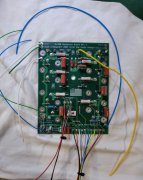
Right
View attachment 86742
View attachment 86743 View attachment 86744
A few comments:
- Check the wire lengths on both left and right boards.
- Right board has wire lengths very short and most likely must be updated:
- GND_IN1, GND_IN2
- Fused_B+_IN
Now is a good time to add a Green wire to the right board at Fused_B+_Out for the DCP board.


