Mr_rye89’s WOPL 400 Build Containment Thread

mr_rye89

Veteran and General Yakker
Joined
Aug 12, 2015
Messages
2,274
Location
Land of Entrapment
Tagline
Lost in the Ozone Again
Okay no power has been applied with transistors in yet. on the PNP columns (where the MJ21195Gs go) I measure a short from the collectors (screws)to the DC ground, which is not tied to the chassis yet. Is this normal?

EDIT: This "short" goes away when I undo the ground buss bar from the big E-capacitors in the power supply. Maybe the low ESR throws my meter off?
 
Last edited:

George S.

Veteran and General Yakker
Joined
Feb 18, 2020
Messages
4,590
Kyle, are you sure that resistor is supposed to be across those test points? I have the next earlier revision of those back planes and thought a 8 ohm resistor goes across the speaker terminals. Have some things to do, then I fire up the desktop and look at the PDF I have.
Have today and tomorrow off after working 69 1/2 hrs in past 5 days. Tired.
 

George S.

Veteran and General Yakker
Joined
Feb 18, 2020
Messages
4,590
Kyle, now looking at the "Backplane Bring Up Recommendations" no date or revisions on it, but it is 83 KB size.
#5 says disconnect the star ground from the chassis stud. Connect the ohm meter ground to the chassis stud and the other lead to B+ and then B- to make sure there is no continuity between the B+ and B- rails and metal chassis. No continuity is good, continuity means a short, bad. There should be only one master ground on the amp, this is it, the star ground, the wire from the buss bar to the chassis stud.
#15 says temporarily attach a 10k ohm between each channel output and DC ground. I put mine directly on the speaker jacks.
Further down the document you'll be disconnecting the star ground again many times as you populate the outputs to check for shorts between the rails and ground.
No where on the document do I see a resistor between two test points
 

Vintage 700b

Chief Journeyman
Joined
Mar 13, 2019
Messages
753
Location
Wisconsin
Tagline
Fabricator
Hey Guys,
Looks right to me. That is how I have always done it on my 700's. See #15.
I may be mistaken with my interpretation of the documentation, but it has worked perfectly for 3 amplifiers, Fully WOPL'd.
At the point in the build that I bring up the backplane, I do not have the DC Protect board installed in the chassis, therefore there is nothing hooked to the speaker output studs/jacks.
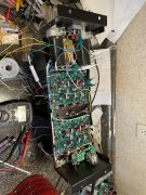
TP3 is provided for that (on the 700 Backplanes). I see the TP next to the outputs on Kyles 400 backplane, can’t tell if it is TP3 or TP 4 on that board, but he has the resistor placed correctly. One of Joe’s innovations that makes testing and troubleshooting these boards so straightforward.

This is from the "Backplane Bring Up Documentation” From Joe:

14. Install ONLY the bottom most row of transistors, starting with the transformer side an MJ21196

in first column, then MJ21195 in second column, then MJ21196 in third column, then MJ21195

in fourth column.

15. Temporarily attach a 10K ohm resistor between each channel output and DC ground.

16. With the one wire from the DC ground bus bar to the chassis standoff tie point temporarily

removed, test for no shorts to the chassis. Test each transistor can for no shorts to the chassis

as well.

17. Bring up wired bare chassis with Variac and DBT......................
 
Last edited:
Top