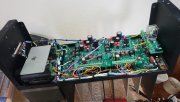
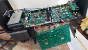
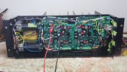
Meet "Val" PL 400 series 1, SN 171xx

Joined
Aug 27, 2022
Messages
134
Location
Ste. Genevieve, MO
#41
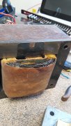
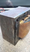
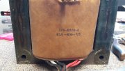
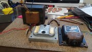
Well, before I place my order to WOA I thought I should check the transformer outputs first. No sense having a beautiful rebuild that can't be used.
Under no load conditions as in Nothing connected to the transformer, my voltages seem a little low
DC = +57.5 and -57.4 from rectifier with 5.7 vac out across the positive and negative output.
AC = 125.7 across the input to the rectifier.
The lo voltage AC reads 5.7vac which seems acceptable.
Input to Transformer is 122.5vac
These voltages are read with the power caps removed. Will that make that much of a difference? Or do I have a bad rectifier?
 

gene french

Veteran and General Yakker
Joined
Mar 6, 2022
Messages
5,563
Location
guayabo de bagaces, guanacaste, costa rica....
Tagline
music...the healer of souls...
#43
Well, before I place my order to WOA I thought I should check the transformer outputs first. No sense having a beautiful rebuild that can't be used.
Under no load conditions as in Nothing connected to the transformer, my voltages seem a little low
DC = +57.5 and -57.4 from rectifier with 5.7 vac out across the positive and negative output.
AC = 125.7 across the input to the rectifier.
The lo voltage AC reads 5.7vac which seems acceptable.
Input to Transformer is 122.5vac
These voltages are read with the power caps removed. Will that make that much of a difference? Or do I have a bad rectifier?
post 3634 in the phase linear 400 thread...
 
Joined
Aug 27, 2022
Messages
134
Location
Ste. Genevieve, MO
#45
Thanks for posting the photo. I saved it as a wiring guide. Which 2 wires are you referring to Gene? The ones for meter lighting? The leads for the thermistor? Both? That's a good idea about the meter taps. I already had figured on connecting to the output side of the DCP. 2 ring terminals should work nicely. Really looking forward to getting those bias transistors off the chassis. I grit my teeth every time I move the control board around.

Placed my order to Joe minutes ago...don't understand why my parts haven't arrived yet...;):D:D

Yes, I'm going for a FULL COMP build.
 

gene french

Veteran and General Yakker
Joined
Mar 6, 2022
Messages
5,563
Location
guayabo de bagaces, guanacaste, costa rica....
Tagline
music...the healer of souls...
#46
Thanks for posting the photo. I saved it as a wiring guide. Which 2 wires are you referring to Gene? The ones for meter lighting? The leads for the thermistor? Both? That's a good idea about the meter taps. I already had figured on connecting to the output side of the DCP. 2 ring terminals should work nicely. Really looking forward to getting those bias transistors off the chassis. I grit my teeth every time I move the control board around.

Placed my order to Joe minutes ago...don't understand why my parts haven't arrived yet...;):D:D

Yes, I'm going for a FULL COMP build.
both...
joe recommends for lighting ac wore routed together to left front corner then to meter....
and ac to thermal cut off underback planes...bundled together...i couldnt do that...lol
i ran it up the middle to the top and over to fuse section....lol
 

Attachments

gene french

Veteran and General Yakker
Joined
Mar 6, 2022
Messages
5,563
Location
guayabo de bagaces, guanacaste, costa rica....
Tagline
music...the healer of souls...
#49
Curious as to why... curiouser as to why you eliminated the bias transistors.
i damaged them during the build....had to wait for the replacements to arrive....that was my first build....
second one went a whole bunch smoother....lol
however, alls well that ends well....
i am no tech....i assure you...
i just enjoy building stuff....
 
Joined
Aug 27, 2022
Messages
134
Location
Ste. Genevieve, MO
#56
another mod...i was made aware of...joe said important but not critical...the two orange wires (pad 5 left and right) are rerouted to the central bus bar also ..
Gene I noticed you don't seem to have a ground on the input ground copper plate tying it to the main busbar. Was there a reason? I'm wondering why have it at all if not for that reason.
 

gene french

Veteran and General Yakker
Joined
Mar 6, 2022
Messages
5,563
Location
guayabo de bagaces, guanacaste, costa rica....
Tagline
music...the healer of souls...
#57
Gene I noticed you don't seem to have a ground on the input ground copper plate tying it to the main busbar. Was there a reason? I'm wondering why have it at all if not for that reason.
its there...on non wopled 400s...mod for dcp install...as per watts instructions....
one my first wopl i ran the same wire...again referring to watts install details...i sent many pics ...
joe saw that wire and asked why i put it there as it is not in his docs ...i responded as per watts install...
to which he told me that the install docs was for adding to non wopl machines...and that wire was not used on wopls...i then removed it.. hence you dont see it...lololol
it is in my phase 400 thread...
 

George S.

Veteran and General Yakker
Joined
Feb 18, 2020
Messages
5,033
#58
In a WOPL build, that wire gets removed, and the plate gets ground through the coax shield from the control board. If that wire was left installed, there would be a ground loop, and potential hum.
That copper plate and RCA's, also needs to be insulated from chassis ground, hence the fiber insulating washers on the RCA's, in origonal configuration or WOPL build.
 
Joined
Aug 27, 2022
Messages
134
Location
Ste. Genevieve, MO
#59
In a WOPL build, that wire gets removed, and the plate gets ground through the coax shield from the control board. If that wire was left installed, there would be a ground loop, and potential hum.
That copper plate and RCA's, also needs to be insulated from chassis ground, hence the fiber insulating washers on the RCA's, in origonal configuration or WOPL build.
So the plate can be eliminated? As long as L/R signal grounds are tied together? Or is that not required as well?
 
Top