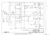
I have two of these amps that I am recapping . One channel on one of the amps is giving me trouble . At first it had real high DC offset(-300ma) then it appear to be oscillating as I had high AC on the speaker terminals . Now it shorts out one or two of the TIP36C output transistors . There is no paper work I can find for these amps so I have been (with the help of AK members) making a schematic . So far I have competed Board B which is the output board see attached picture. I am working on Board C which appears to be a protection circuit and then Board A which is the power supply . There are no relays or chassis ground connections(that I can find) in these dual mono designed amps. My AK thread is" DC OFFSET question" in Vintage Solid State forum which is very busy so my thread is getting buried.Any Ideas on what it could be ? Thanks

You are using an out of date browser. It may not display this or other websites correctly.
You should upgrade or use an alternative browser.
You should upgrade or use an alternative browser.
Martex M200 amps
- Thread starter calman46
- Start date
CASSETTE DECK
Chief Journeyman
- Joined
- Jun 20, 2013
- Messages
- 696
- Location
- Kapiti Coast, New Zealand
- Tagline
- Path under Coastlands overbridge
Check the 10 ohm 1 watt resistor in series with 100nF capacitor on the amplifier module speaker output. The zobel network helps to prevent self oscillation.
The last time I had a problem with an amplifier module oscillating, this resistor was found to be open circuit.
I replaced the resistor and the oscillation problem was solved.
The last time I had a problem with an amplifier module oscillating, this resistor was found to be open circuit.
I replaced the resistor and the oscillation problem was solved.
Last edited:
- Joined
- Jan 14, 2011
- Messages
- 75,398
- Location
- Gillette, Wyo.
- Tagline
- Halfbiass...Electron Herder and Backass Woof
What are the specs on your zoebel inductor? How fast are your drivers compared to your outputs?
I would have to set up a test for the inductor ,I have no specs. I do know there is continuity on the inductor . The drivers and outputs are the orignal design components and the other side is working .
Do you mean when you replace the TIP36 transistors they short again on power up?
One TIP 36C shorted this time. It didn't happened right away . I was watching the DC offset (original problem) its was high at -123mV but it was adjusting to zero and at -80mV I had 52vDC on the speaker terminals,I shut down . Someone had worked on this board before connected both right and left(return path?) negative Inputs together and then to chassis . I had to remove it to work on the boards . I thought it was for a better chassis ground so I only replaced the chassis ground end , which did nothing as these amps don't have a chassis ground. I'm thinking on putting that jumper back the way it was maybe something is wrong in the negative return path on this board? I 'm not sure how clear my explanation is . I'm still working a schematic for Board C so the amp is apart .
Last edited:
I think it might be Q5 (40594) causing the problem . I removed it measured the hfe and its 10 ,the specs have min. 70 . With such low gain on the 94 would the transistor work correctly ? Anybody have any 40594's. The hfe of the 40595 is 192 .
- Joined
- Jan 14, 2011
- Messages
- 75,398
- Location
- Gillette, Wyo.
- Tagline
- Halfbiass...Electron Herder and Backass Woof
In most instances , audio especially, more gain is better. Whether a gain of 10 is going to operate in circuit corre tly is out of my league. Wouldn't take much to find out though, if the volt and current specs are at least or better than the 4 I would say try it.
- Joined
- Jan 14, 2011
- Messages
- 75,398
- Location
- Gillette, Wyo.
- Tagline
- Halfbiass...Electron Herder and Backass Woof
Are the 40594's an RCA?
- Joined
- Jan 14, 2011
- Messages
- 75,398
- Location
- Gillette, Wyo.
- Tagline
- Halfbiass...Electron Herder and Backass Woof
Check the specs on the 2N3439's and the 2N5416's they might just work as the pre-drivers...
Yes both 95/94 are RCAAre the 40594's an RCA?
- Joined
- Jan 14, 2011
- Messages
- 75,398
- Location
- Gillette, Wyo.
- Tagline
- Halfbiass...Electron Herder and Backass Woof
Compare with the 39's and 16's, might be surprised.
I put in the 2N3439/ 2N5416 and they work but the DC offset is still high . I have amp on a DLT and at turn on this side is -150mV . I have been comparing voltage readings with the other side and there the same so far. I did find an error with my schematic. The 740 resistor on Base of Q3 is really a zener diode with band markings yellow, brown , violet . 4.1V ? I get -3.8v across it . I have let the offset go to -120mV when it starts to struggle (dim bulb tester in circuit) . Where should I be checking/comparing voltages any suggestions ? These are different from what I am use to . I have to use two meters to take readings as there no common chassis ground point . I use the center tap of the secondary of each transformer. Thanks and Happy New !!!
- Joined
- Jan 14, 2011
- Messages
- 75,398
- Location
- Gillette, Wyo.
- Tagline
- Halfbiass...Electron Herder and Backass Woof
Time for Joe...
- Joined
- Jan 14, 2011
- Messages
- 75,398
- Location
- Gillette, Wyo.
- Tagline
- Halfbiass...Electron Herder and Backass Woof
How do you bias these??
Time for Joe...
Will have to wait for Friday. Just got home...
- Joined
- Jan 14, 2011
- Messages
- 75,398
- Location
- Gillette, Wyo.
- Tagline
- Halfbiass...Electron Herder and Backass Woof
Trip??