
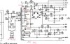
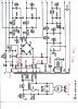
I'm looking into the possibilities of making a power transformer for my model 18 . I have the original E & l laminates . There are no AC voltages on 18 schematic but I'm told I can use the the ones on the model 19 . The primary on the 18 was two coils in parallel , I was going to use 1 . Its the secondary that raises issues ,as it is drawn all the taps share the same CT is that right? I may omit the HV winding for the scope (transformer's Achilles Heal ) there is an work around for adding another transformer (looking into it) . Do you think its feasible to make one ? I'll post the schematic shortly . Thanks
Attachments
-
 21.3 KB Views: 41
 -
 91.1 KB Views: 36
Last edited:
")