- Joined
- Jan 14, 2011
- Messages
- 75,813
- Location
- Gillette, Wyo.
- Tagline
- Halfbiass...Electron Herder and Backass Woof
Yep, you can check for shorted outputs in circuit.

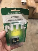
Today ended up being “speaker day”. I did bring a scrap piece of MDF in the house and set up a work station on the kitchen table for PL surgery though. I have a pretty good handle on checking the power supply so I might do that quick. What did these use for a bridge rectifier? It just happens I have pic related in stock... NTE5326. I will also double check the rail fuses. I had the 5a wire filament automotive fuses in it. Years ago I really abused Linda, 8a flat filaments and popped them like popcorn yet I never blew a main...The power supply might be affected if the mains went and the rail fuses didn't. I would lean towards the bridge rectifier. I have never seen a bad transformer, although it has hapoened.
Today ended up being “speaker day”. I did bring a scrap piece of MDF in the house and set up a work station on the kitchen table for PL surgery though. I have a pretty good handle on checking the power supply so I might do that quick. What did these use for a bridge rectifier? It just happens I have pic related in stock... NTE5326. I will also double check the rail fuses. I had the 5a wire filament automotive fuses in it. Years ago I really abused Linda, 8a flat filaments and popped them like popcorn yet I never blew a main...
gimme a little time to sort things, been busy as heck. I have to take advantage of my friends help with the speaker build and when I get into one of these amps I want to be able to focus on it as its basically my PL (electronics for that matter) cherry. Probably old hat you you guys but I could mess stuff up quick!
The DC offset spec in the Phase Linear 700 service manual (for serial numbers 0 thru 773-200) stated:
"using a voltmeter, adjust the offset controls so that the meter indicates 0 (zero) volts at the speaker terminals between hot and ground. The controls are readily adjusted simply by using the index finger and thumb, reaching down through the top of the amplifier. Adjust as follows:
A) Set the input mode switch to A.C. coupling.
B) Rotate the level control fully counterclockwise (level down) and adjust output offest for 0 (zero) volts.
C) Rotate level control fully clockwise and adjust input offset for 0 (zero) volts. This completes offset