Jimmy's 400 Rev D in for Warranty

laatsch55

Administrator,
Staff member
Joined
Jan 14, 2011
Messages
74,124
Location
Gillette, Wyo.
Tagline
Halfbiass...Electron Herder and Backass Woof
#1
Survived the DBT test. Straight to the wall ....bias was way high, in the high 400's, offset -22mv left, -18mv right. Bias adjusted to the lower limit on the left gives 405 , on the right 357. Original backplanes, Rev D board. Afterr 5 minutes or so the relay clicks and full positive rail voltage to both outputs...
 

Attachments

laatsch55

Administrator,
Staff member
Joined
Jan 14, 2011
Messages
74,124
Location
Gillette, Wyo.
Tagline
Halfbiass...Electron Herder and Backass Woof
#3
I don't think so, it's not blowing fuses, and it has a DCP board that works...
 

62vauxhall

Veteran and General Yakker
Joined
May 14, 2014
Messages
2,277
Location
Southwest Kootenays BC
Tagline
No such things as bad days, just bad moments
#4
When I read full rail voltages to both outputs I assumed that to mean speaker outputs like at the binding posts.
 

laatsch55

Administrator,
Staff member
Joined
Jan 14, 2011
Messages
74,124
Location
Gillette, Wyo.
Tagline
Halfbiass...Electron Herder and Backass Woof
#6
If I don't touch it , it does not go to rail voltage, however, should I touch the board or twist it....then she goes..
 

62vauxhall

Veteran and General Yakker
Joined
May 14, 2014
Messages
2,277
Location
Southwest Kootenays BC
Tagline
No such things as bad days, just bad moments
#7
I’ll be following this thread. You may remember I wound up with an opportunity buy 4 fin 400 A year and a half ago. Glen helped out with a REV C or D board and different outputs. Still original back panes though. It did not (yet) get a DCP board because I thought 400’s were less needy of them than 700’s.
 

WOPL Sniffer

Veteran and General Yakker
Joined
Aug 10, 2015
Messages
11,223
Location
Minnie-Soda
Tagline
Screw it
#8
I’ll be following this thread. You may remember I wound up with an opportunity buy 4 fin 400 A year and a half ago. Glen helped out with a REV C or D board and different outputs. Still original back panes though. It did not (yet) get a DCP board because I thought 400’s were less needy of them than 700’s.
DC on either 400 or 700 speaker jacks will blow up speakers with equal ease... Even though the rail voltages are different speakers can't handle either.

TICK TICK TICK......
 

62vauxhall

Veteran and General Yakker
Joined
May 14, 2014
Messages
2,277
Location
Southwest Kootenays BC
Tagline
No such things as bad days, just bad moments
#9
DC on either 400 or 700 speaker jacks will blow up speakers with equal ease... Even though the rail voltages are different speakers can't handle either.

TICK TICK TICK......
I hear ya. Glen and I spoke not too long ago and he offered me a protect board. I guess i should take him up on it.
 

mlucitt

Veteran and General Yakker
Joined
Jun 24, 2011
Messages
3,339
Location
Jacksonville, FL
#12
I thought our new design WOA Control Boards would not allow the matched pair or OPAMP in the front end to "latch up" and send rail voltage to the speaker outputs. Of course, this one has a mechanical problem (broken solder joint, etc.), but is this the first WOA Control Board to have the dreaded rail voltage on the output issue?
 

laatsch55

Administrator,
Staff member
Joined
Jan 14, 2011
Messages
74,124
Location
Gillette, Wyo.
Tagline
Halfbiass...Electron Herder and Backass Woof
#13
No...
Short q7 or 10 , among other things and you have rail voltage on the outputs..
 

oldphaser

Chief Journeyman
Joined
Sep 8, 2012
Messages
845
#14
If I don't touch it , it does not go to rail voltage, however, should I touch the board or twist it....then she goes..
Lee,

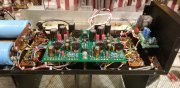
You didn't mention which board you were touching so I will assume it is the Rev D board and not Don's DCP.

Follow the disassembly procedure in the Phase Linear 400 service manual.....

"Remove the (2) hold-down nuts from the Rev D board, flip the circuit board over and gently pull towards you. Before energizing the unit be sure that none of the PCB components are touching the rim of the chassis. "

The unit is now ready to be powered on.

Dean taught me many years ago to use the handle of a screwdriver and tap the side of the pc board to locate any intermittent's which may be caused by bad solder joints, traces, defective components, etc. We also heat and cool parts on the pc board to locate defective parts. Dean used the tip of a soldering iron placed in close proximity to parts to heat them as well as a circuit cooling spray to cool them.

The original wiring between the pc board and output stage when it is subject to flexing will start to break individual strands off and can also cause problems.

I was recently working on an 400 II amp while the owner was standing next to me and I broke one of the B+/B- wires leading to the pc board (due to flexing the board several times after performing the low THD mod and upgrading some parts on the pc board) and didn't see it right away. When I powered it back up one of the rails was not powering up and the sine wave was severely clipped on my oscilloscope. I remained calm and I told the owner that I had suspected one of the wires was bad and quickly located it. When the owner first showed up he mentioned some problem that was common to both channels and I took a look at the power supply filter caps. One of them was a FAO brand and the other was a replacement that occurred some time in its life and told him that the FAO brand had a higher than normal failure rate and was more than likely the culprit. Indeed when I measured both caps the replacement was measuring around 85 volts the FAO was at approx. 45 volts. That was a quick and easy fix as well.

As you probably already know, the 2N3403 bias transistors leads are also subject to breakage due to flexing of the leads as well.


Ed
 
Last edited:

laatsch55

Administrator,
Staff member
Joined
Jan 14, 2011
Messages
74,124
Location
Gillette, Wyo.
Tagline
Halfbiass...Electron Herder and Backass Woof
#15
Standard backwall, quasi Rev D White Oak board. I suspect a bad solder joint. The original point to point was replaced with the Navo special silver coated teflon...
 

oldphaser

Chief Journeyman
Joined
Sep 8, 2012
Messages
845
#16
Standard backwall, quasi Rev D White Oak board. I suspect a bad solder joint. The original point to point was replaced with the Navo special silver coated teflon...
Lee,

Another trick Dean taught me.......

On the "standard backwall" use a pair of needle-nose pliers and try pulling on the bus wires next to each solder joint connection on the TO-3 sockets. Sometimes there are cracked/poor solder joints.

You might also consider replacing all of the 10 ohm carbon composition resistors on the backwall as well. These 10 ohm resistors are going up in value with age and do not give a very good "static measurement" of the bias voltage as they go up in value. Ideally they should be very close to the nominal 10 ohms and matched to either other in value so you get consistent measurements between each other.
Dean and I use a "dynamic measurement" of the bias by looking at the crossover notch at around 1KHz or 2KHz at 1 watt (2.83 V into 8 ohms) on an oscilloscope (fed from the output of a distortion analyzer) and adjust the bias as a compromise between the amplifier after being in both a hot and cold state.

Ed
 
Last edited:

laatsch55

Administrator,
Staff member
Joined
Jan 14, 2011
Messages
74,124
Location
Gillette, Wyo.
Tagline
Halfbiass...Electron Herder and Backass Woof
#17
I replaced the bias resistors when I put the WO board in Ed. Dale, 10 ohm..2 watt..
 

laatsch55

Administrator,
Staff member
Joined
Jan 14, 2011
Messages
74,124
Location
Gillette, Wyo.
Tagline
Halfbiass...Electron Herder and Backass Woof
#20
The frustration continues...got a blizzard comin, all my wells tucked in for a 3 day storm if it gets that bad. 9- 20 Inches of snow and 60 mph winds....this should be fun.

Jut a slight movement of the upper right corner of the board....
 
Top