I want to White Oak a Phase Linear 400 Series I

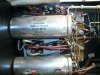
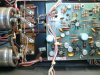
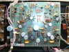
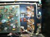
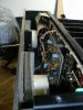
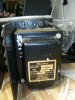
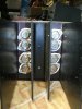
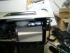
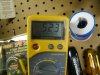
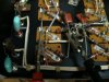
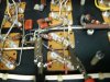
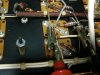
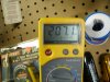
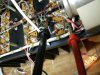
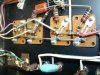
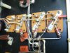
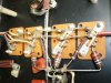
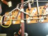
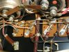
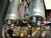
I have had to completely remove the heatsinks and press the little dried up wad of grease out through the chassis next to the transistor socket. I watch them roll down to the bottom of the amp where they collect in heatsink compound heaven (or is it hell?). Then I use a Q-tip to coax all the grease out from between the socket and the chassis. I use an old TO-3 transistor lead soldered onto a steel rod to check and see if the socket connectors are still gripping. Rather than replace a socket, I just push the connector spring contacts together with some needle nose pliers until the transistor lead just starts to drag a bit. I think the transistor leads are .038" minimum.

Mark
 
Is WD-40 or alcohol the better solvent to remove the old thermal compound? I lucked up on the one I was re-working.. It only had silpads with NO GREASE at all. I was one lucky guy on that front..but I have the second 400 which should arrive tomorrow...so I was just curious..
 
I have never tried WD-40 for it. Not sure what residue that leaves behind. The alcohol works pretty well and it comes out degreased afterwards.
 
Why does everyone apparently prefer mica and thermal compound to plain silpads? This may be a stupid question, but I'm just wondering...MCM Electronics has silpads available I think...
 
The mica with grease provides a better thermal interface than the silpads do. Along with that comes the mess. A tradeoff. If you are not running your amp at Mach 8 it does not matter much.
 
A little mess for a moment, then done. After you wrap it up, you want best performance, so mica and grease is the way to go, imo.
 
I think it is cool to put rocks in your amp. Mica is a rock, no? Actually, Joe is right - tests have been done and mica is the best at transferring heat and those thin sheets are tough. Silipads have been know to cut through on a sharp edge and they have much less electrical insulating effect when they are torn.

Plus, you ca reuse the mica. Silipads are not meant to be reused.
 
Me too Lee, I just trash them and start with fresh. My mules have Silpads since I use these to swap devices and I do not want the mess.
 
I have tried everything, from steaming hot water over the sink, acetone, MEK, isopropal, citrol, WD-40, but what works the best is some good ol condensate, fresh from the volume tank on a green oil well. Very dangerous, has a flash point of 105 degrees but boy does it cut it. Works great as a penetrant. Damn stuff evaporates so fast I think it takes other substances with it.
 
The Phase Linear 400 for the second rebuild arrived today. I am adding some pictures of the "before The faceplate obviously had been in pretty great shape until the UPS guys DROPPED THE BOX. Now I have a bent corner. I am sure there is a proen way to straighten bent corners. The one on eBay has a drop dent in the same place....upper left corner. Most have something with the weight distribution (or some stupid ass dumb F*&^). Anyway, this amp appears to be a later production than the previous one...it has a checksheet with initial on it... Someone tell me the best way to straighten this drop dent out. I am assuming a rubber mallet, but there is probably a better way.

The amp has some dust bunnies but I don't see anything fried....it was missing a fuse cap...(you can tell the replacement one in one of the pics).. Looks pretty nice inside, and I did DBT it, and the bulb went from bright to almost off, but I haven't replaced the fuse yet, nor have I hooked a preamp and speakers yet. I do plan on listening to this one before starting to change anything out. I hope she plays. She was guaranteed not to be DOA..

Anyone want to see any other nudies? Suggestions on measurements you'd like to see?

Let me know. I am going to slow down and take my time on this one..
 

Attachments

  • GEDC0201.JPG
    GEDC0201.JPG
    2.2 MB · Views: 174
  • GEDC0202.JPG
    GEDC0202.JPG
    2.5 MB · Views: 151
  • GEDC0203.JPG
    GEDC0203.JPG
    2.9 MB · Views: 162
  • GEDC0204.JPG
    GEDC0204.JPG
    3 MB · Views: 158
  • GEDC0205.JPG
    GEDC0205.JPG
    3 MB · Views: 141
  • GEDC0206.JPG
    GEDC0206.JPG
    2.9 MB · Views: 135
  • GEDC0207.JPG
    GEDC0207.JPG
    2.4 MB · Views: 146
  • GEDC0208.JPG
    GEDC0208.JPG
    2.5 MB · Views: 141
  • GEDC0209.JPG
    GEDC0209.JPG
    2.6 MB · Views: 136
  • GEDC0210.JPG
    GEDC0210.JPG
    2.6 MB · Views: 142
  • GEDC0211.JPG
    GEDC0211.JPG
    2.2 MB · Views: 146
Sorry about the bent corner, Lee knows how to fix those.
How can the guy say guaranteed not DOA when it is missing a fuse cap? To me that is de facto DOA (in one channel). Also, people pull fuses for a reason. If there is a problem in that amp it WILL be associated with the Right channel, if that is the fuse cap you replaced the picture was a little blurry.

The driver and output transistors look original although I think they have been removed and regreased. The output transistors date from the 19th week of 1975, so your amp had to be made shortly after that date.

It would be good to know the rail voltages. You can check that with both of the small 5 AGX fuses removed. You know how to do that.

Mark
 
Warm the corne up with a heatshrink heat gun or one of your wife's 5KW hair dryers, until you can't hold on to it anymore. Duckbilled visegrips with softjaws on each side(wood, another piece of alum, etc), and tighten the vise grips. you want to rig up on it so the duckbills are the hypotenuse of that corner. We heat it up to lessen the chances of the aluminum separating. I do not recommend any heat source capable of more than halfway to aluminums melting point. (1221Deg F.)
I have not had it effect the anodizing yet, but I just took the chill off mostly.


Going slow and taking your time is good, BUT, doing what's recommended IN THE ORDER IT WAS STATED is even better.

My first test? DC offset, 2nd? Bias. Tells ya a lot about what kind of shape it's in. Do those first.
Was the fuse cap in the box in pieces? If it was dropped hard enough to bend the faceplate, a -"not fully engaged" fusecap could dislodge.
 
A heat gun I have...

http://www.harborfreight.com/1500-watt- ... 96289.html


and it will get hotter that the hinges of hell. It's a Harbor Freight ite that I use to get the old wrap off drums. So I get the corner hot...hot...and then use a visegrips with wood or something that won't mar the surface while tightening the vise down. Kevin is very mechanical and I'll try to get him to help me...

DC offset..where and how do I test that...I'll need some handholding...Rail voltages are 74.4 and -74.4 methinks. I'll try to get those readings in the morning and take some pictures,, Also where and how do I get bias? MARK???? Lee????

Also noticed all the resistors on the driver transistors have been changed to smaller ones. I don't know what the guy was doing, but they look like 1 or 2 watt ones. I'll try to get a pic.......what value and wattage are the resistors speced to be?

The resistors on the outputs seem to be stock. The PCB appears to be stock..

I'll look for the fuse cap and fuse....
 
1 watt , 150 ohm.

Dc offset is measured at the speaker outputs with your meter on DC volts. You'll be measuring in the low MILLIVOLTS so the lowest setting on your meter. Positive lead from the meter to the positive speaker output. The negative lead from the meter to the negative speaker output.

Before doing the next test, unbolt the board and lay it out , with the solder side looking up. Put a piece of tape over the edge of the chassis the the board is hanging over, it's not if but when you short something out if you don't. Support the outside of the board with an old toilet paper tube or similar non conductive and relatively expenendable substitute.

Bias is measured on each side of R38, 39 on the transistor wall. Positive lead from the meter to the base bus bar on the far left row of tranny's the far left bus bar, the negative lead from the meter to the common point of the emitter resistors between the two rows of tranny's. That is a 10 ohm 1 watt resistor. That is the positive rail you are measuring, if you'll look at the next row of tranny's to the right there is another 10 ohm 1 watt resistor from the common tie point of emitter resistors for the negative row of output to the base bus bar .. Again you are looking foe MILLIVOLTS DC. Hook up your meter leads AFTER POWERING OFF AND DISCHARGING THE POWER SUPPLY CAPACITORS WITH YOUR DISCHARGING RESISTOR you've built already. Remove the meter leads AFTER POWERING OFF AND DISCHARGING THE POWER SUPPLY CAPACITORS WITH YOUR DISCHARGING RESISTOR. Both of these measurements will be with no input or output connections made to anything. Post the results in your next post.
Also I didn't get an answer for this;Was the fuse cap in the box in pieces? If it was dropped hard enough to bend the faceplate, a -"not fully engaged" fusecap could dislodge.
 
Sutton. If you need help on that face plate bring it down to the house and I can fix that for ya !
 
Thanks Kevin. Just take the chill off so it doesn't want to pull away from itself.
 
Yea... No prob. Aluminum is funny stuff. Its kinda like Sutton.... Has a mind of its own.. lol.. I think I could make a face plate if I knew how to put the writing on them....
 
OK..I just fired the amp up again, and it blew the right output fuse. Measured the output at the speaker terminals...I got 33 microvolts? I'm not sure where the decimal goes. On the right channel I got 120V...so I'm not sure where the problem is, but there is one.

Also there was no fuse holder cap in the box, so this has been a problem, obviously..

I've put some pics below, maybe somebody can see something. Do the resistors on the drivers look right? Best I can tell they measue in the 150-154 ohm range...so they may be stock...

The filter/ storage caps read like they are 4500 mH caps....not all over the place like the ones from the previous amp...

I need to find a schematic so I know where R38, R39....etc are.....hopefully I can decipher a schematic...I can probably fumble my way through it...
 

Attachments

  • GEDC0228.JPG
    GEDC0228.JPG
    2.5 MB · Views: 140
  • GEDC0227.JPG
    GEDC0227.JPG
    2.3 MB · Views: 185
  • GEDC0226.JPG
    GEDC0226.JPG
    2.4 MB · Views: 110
  • GEDC0225.JPG
    GEDC0225.JPG
    2.6 MB · Views: 113
  • GEDC0224.JPG
    GEDC0224.JPG
    2.5 MB · Views: 111
  • GEDC0223.JPG
    GEDC0223.JPG
    2.5 MB · Views: 114
  • GEDC0222.JPG
    GEDC0222.JPG
    2.4 MB · Views: 110
  • GEDC0221.JPG
    GEDC0221.JPG
    2.5 MB · Views: 114
  • GEDC0220.JPG
    GEDC0220.JPG
    2.7 MB · Views: 108
  • GEDC0219.JPG
    GEDC0219.JPG
    2.6 MB · Views: 113
  • GEDC0218.JPG
    GEDC0218.JPG
    2.6 MB · Views: 111
  • GEDC0217.JPG
    GEDC0217.JPG
    2.8 MB · Views: 115
  • GEDC0216.JPG
    GEDC0216.JPG
    2.7 MB · Views: 108
  • GEDC0215.JPG
    GEDC0215.JPG
    2.6 MB · Views: 121
  • GEDC0214.JPG
    GEDC0214.JPG
    2.5 MB · Views: 124
I'm not sure if I measured at the right places or not, but the pic above has the result in the pic below. Looks like one bank is reading 0.0 and the one beside it is reading 200+ mv. The two to the left...near the input outputs...read .45 and .52 mv. If my probes are in the correct place...The one channel is blowing fuses as well and reads like a wall outlet..at the speaker output..
 
Back
Top