Glen builds a 700B

grapplesaw

Veteran and General Yakker
Joined
Aug 13, 2014
Messages
2,786
Location
Vancouver
Tagline
---
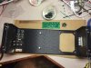
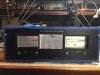
So I have never owned a B series anything before. And now I have a silver and soon to be alive Black beauty

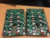
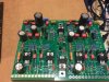
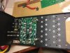
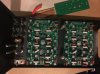
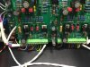
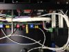
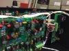
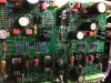
It came to be after looking at a lot of WO parts in the drawer and with the help of many Forum members I collected up the parts. A new black face plate from Perry. The transformer came from an old B chassis I got from Lee a while back. I had some goodies from Joe. A new chassis, Back plates, control board rev E-2 and some new heat sinks. The power caps and wire from Dennis. Meterface plates from Ed. DCP board from Don, don’t leave home without one. So it was a fly

The only used parts are the Meter bezels and power transformer.

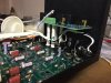
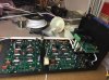
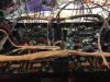
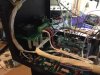
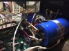
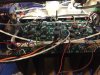
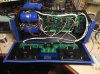
Photos are in next post
 
Last edited:
It starts with new stock
 

Attachments

  • DE57D23A-5B32-4D9D-9EF5-AFCDBDA3BA83.jpg
    DE57D23A-5B32-4D9D-9EF5-AFCDBDA3BA83.jpg
    20.7 KB · Views: 65
  • 65355830-F323-4A0F-9440-DAB1ADD012E2.jpg
    65355830-F323-4A0F-9440-DAB1ADD012E2.jpg
    20.8 KB · Views: 47
  • 37E92370-57DD-4360-A45A-00BA77FB526D.jpg
    37E92370-57DD-4360-A45A-00BA77FB526D.jpg
    19.9 KB · Views: 44
  • B28D7D4B-8990-43AB-A7BB-61127441E410.jpg
    B28D7D4B-8990-43AB-A7BB-61127441E410.jpg
    20 KB · Views: 44
  • ECE3F052-F9B4-424D-A488-E4368798FEF9.jpg
    ECE3F052-F9B4-424D-A488-E4368798FEF9.jpg
    19.8 KB · Views: 48
Starting to take shape
 

Attachments

  • D8ADAB4E-C090-4E6F-986C-3318EAA27AE7.jpg
    D8ADAB4E-C090-4E6F-986C-3318EAA27AE7.jpg
    20 KB · Views: 45
  • C6FCB226-5B10-4001-87F4-7C9FE0870499.jpg
    C6FCB226-5B10-4001-87F4-7C9FE0870499.jpg
    20.2 KB · Views: 45
  • 968C5E8D-2866-432C-8A3D-51DA773657D8.jpg
    968C5E8D-2866-432C-8A3D-51DA773657D8.jpg
    20.6 KB · Views: 45
  • 44A43CBA-BD08-4179-9FBA-F5EA22D380C1.jpg
    44A43CBA-BD08-4179-9FBA-F5EA22D380C1.jpg
    20.5 KB · Views: 43
  • 24C007F9-E6EE-45CF-844F-8C67A641C7BF.jpg
    24C007F9-E6EE-45CF-844F-8C67A641C7BF.jpg
    20.1 KB · Views: 44
  • 99FA7AB3-7429-4B59-B916-4A1E61CC6A19.jpg
    99FA7AB3-7429-4B59-B916-4A1E61CC6A19.jpg
    20.5 KB · Views: 40
Final assembly. Ready to test
 

Attachments

  • 6F1C35DE-C751-4801-AFE3-6A0A9CA510BD.jpg
    6F1C35DE-C751-4801-AFE3-6A0A9CA510BD.jpg
    20.5 KB · Views: 57
  • 709EDD9D-5E65-4EDE-8B28-1D6EF1CE1F8D.jpg
    709EDD9D-5E65-4EDE-8B28-1D6EF1CE1F8D.jpg
    18.4 KB · Views: 54
  • 6828D0B7-4664-49CE-9AE9-9726DC614056.jpg
    6828D0B7-4664-49CE-9AE9-9726DC614056.jpg
    20.6 KB · Views: 46
  • DB683B24-F074-434E-9574-B04B8966B199.jpg
    DB683B24-F074-434E-9574-B04B8966B199.jpg
    19.7 KB · Views: 44
  • EBBE359F-8891-41FE-8A29-702B4EDBC6FC.jpg
    EBBE359F-8891-41FE-8A29-702B4EDBC6FC.jpg
    20.7 KB · Views: 43
It shall kill
 

Attachments

  • AE1026A8-C26B-49CA-8A10-532A410A01E6.gif
    AE1026A8-C26B-49CA-8A10-532A410A01E6.gif
    1.6 MB · Views: 49
Glen, I am impressed. Your first post was at 9:28 and the last was 9:48. A righteous bit work in 20 minutes....not bad at all!
 
Its alive, sorta. Powered up with dim bulb and no output drives. At this point the Right channel was it tiny bit brighter when powering up through the DBT with Rail fuses installed. Then I saw bias good on right but left fell off to 58 mv. It drops from 300 mv after 60 rail volts. It came back if I dropped below 60v and basicly disappeared at full viltage. DCP checked out good. Unhooked power to front end with no change. Pulled bias trans and checked ok. Looks like protection circui I guess.
Have a look at video. Bias top meter, positive rail voltage in the middle. Any suggestion welcomed.
 

Attachments

So here is shot of the control board. If anyone sees a problem speak up please. I did tweek the C8 and C9 to a little higher roll off point. 103pf combined.

So so did I miss something? Is there any performance upgrades to had. Some talk about lower signal to noise ratio and better cross talk separation maybe? I could be crazy but never know unless you ask. I must be crazy if i keep building these things or that’s what my wife sayes.


Attachments

  • image.jpg
    image.jpg
    101.5 KB · Views: 39
Last edited:
So here is shot of the control board. If anyone sees a problem speak up please. I did tweek the C8 and C9 to a little higher roll off point. 103pf combined.

So so did I miss something? Is there any performance upgrades to had. Some talk about lower signal to noise ratio and better cross talk separation maybe? I could be crazy but never know unless you ask. I must be crazy if i keep building these things or that’s what my wife sayes.


Those are the 2 caps along with C14 that you should definitely not mess with Glen. Those were carefully SPICE modeled to provide max bandwidth with assured stability. Be careful.
 
Those are the 2 caps along with C14 that you should definitely not mess with Glen. Those were carefully SPICE modeled to provide max bandwidth with assured stability. Be careful.
Thanks Joe. I will check it out on the scope as soon as I get this running

Perry tells me I have not got latest cap configuration on Back plates so please send me the latest release notes and BOM for them so can upgrade please.

I am am troubled by the bias dropping as rail voltage rises past 60 volts. No ground fault and must be related to bias transistor as it gradually drops with increase volts. Not sure what the heck is going on there. Going to populate first row and then see what happens.

Perry can clarify but I believe he is referring to the fact that the electrolytic caps should not be populated. The documentation specifically calls that out.
 
Yup, just went through the BOM (not that I had to since I just built 50 amps).... C1/C2 do not get pop'd......

I think you have a resistor in backwards.....


HUH??????
 
Yup, just went through the BOM (not that I had to since I just built 50 amps).... C1/C2 do not get pop'd......

I think you have a resistor in backwards.....


HUH??????

dam I hate that. Those pesky resistors cannot be trusted

I am clear now on caps
 
" Those pesky resistors cannot be trusted" I agree..... But I'm laying off the politics........
 
Thanks Joe. I will check it out on the scope as soon as I get this running

Perry tells me I have not got latest cap configuration on Back plates so please send me the latest release notes and BOM for them so can upgrade please.

I am am troubled by the bias dropping as rail voltage rises past 60 volts. No ground fault and must be related to bias transistor as it gradually drops with increase volts. Not sure what the heck is going on there. Going to populate first row and then see what happens.

Bias good after putting in the first row transistors . So I will load the outputs.

As to changing out caps at this time not sure if I will. I have 5 others configured the old way so will deal with it later
 
dam I hate that. Those pesky resistors cannot be trusted

I am clear now on caps

If you blow a rail fuse, one of those polar electrolytics will vent on you shortly after the fuse blow. The backplane configuration should be bipolar caps only (i.e. mylar).
 
As we used to say in the Navy..... Arrrrg, thar she blows.... Arrrrrrr (all said in a proper pirate voice)....


HUH?
 
Finished except for the caps removal

Ok all done. Full testing tomorrow. I will heed Joe’s advice and remove the caps first.
 

Attachments

  • 759A675F-E890-437F-A109-B280C3ABEC08.gif
    759A675F-E890-437F-A109-B280C3ABEC08.gif
    1.4 MB · Views: 31
  • C9C67F81-3FEC-485F-81AF-00C06E2EE447.gif
    C9C67F81-3FEC-485F-81AF-00C06E2EE447.gif
    1.8 MB · Views: 21
  • 521543B6-C18F-4742-B6CF-98C90053342C.gif
    521543B6-C18F-4742-B6CF-98C90053342C.gif
    1.5 MB · Views: 19
If you blow a rail fuse, one of those polar electrolytics will vent on you shortly after the fuse blow. The backplane configuration should be bipolar caps only (i.e. mylar).

Two questions, my curiosity

first - would using a bypolar electrolytic cap in place be ok then

second - using a cap of this size make sense size wise but will it be missed? It got in there to begin with for a reason right?
 
Back
Top