Further upgrading my first built WOPL, a 400 S1 8 fin, with a few goodies.

gene french

Veteran and General Yakker
Joined
Mar 6, 2022
Messages
5,608
Location
guayabo de bagaces, guanacaste, costa rica....
Tagline
music...the healer of souls...
#61
diesel is hard to beat...lol
i only have a 4.5kw setup....about 20 amp @ 230v continuous as long as you get 1000w/m2 of solar radiation...
10 solar panels dedicated to your tesla will keep it charged averaging 15000 miles per year....
so...yes...and no....depending on your driving...
lol

1652653178936.png
this was yesterday....and remember that i only produce what i consume....it is capable of much more....but i dont need it....no a/c or heat here...
and we have gas stove....
the extra panels help out in less than sunny days...
you can see the panels start out before 6am and by 8am are keeping up with my load...until about 4 pm and dead in the water by 6pm...
ymmv...
 

J!m

Veteran and General Yakker
Joined
Dec 24, 2019
Messages
11,133
Location
Connecticut
Tagline
BOT
#63
Fusion reactor. Only way to go.

Not fission.

Hydrogen is extremely reactive- I.e. easy to ignite. Also the fastest burning gas- why it’s popular for rockets escaping gravity.

You have seen “average” drivers… you want them playing with hydrogen?!?
 

gene french

Veteran and General Yakker
Joined
Mar 6, 2022
Messages
5,608
Location
guayabo de bagaces, guanacaste, costa rica....
Tagline
music...the healer of souls...
#64
Bob Carter, Toyota’s Senior Vice President for Automotive Operations, stated in a recent speech to the Automotive News World Congress that hydrogen tanks are bulletproof when it comes to small caliber weapons. And the tanks are even safe when it comes to larger caliber bullets.


According to Carter, “They’re safe. In testing, we fired small-caliber bullets at the hydrogen tank and they just bounced off it. It took a 50-caliber armor-piercing bullet to penetrate the shell. And, even then, it just left a hole and the hydrogen simply leaked out. This is no Hindenburg.


“They’re also viable in real-life conditions. We’ve battle-tested our fuel cell vehicle in the deep freeze of Yellowknife, Canada, the stifling heat of Death Valley, the high altitude of the Rocky Mountains, even the steep hills of San Francisco.”


So, for the naysayers and opponents , it’s time to stop comparing hydrogen cars to the Hindenburg. Hydrogen fuel cell vehicles are safe, viable and will be covering the map in a very short time.
***************
hydrogen...most abundant element in universe...
split water....burn the two by products and you have your water back...
i remember writing a paper on this for one high school project...
lol
 

J!m

Veteran and General Yakker
Joined
Dec 24, 2019
Messages
11,133
Location
Connecticut
Tagline
BOT
#65
It’s not that simple. Car crashes are not .50 rounds at high speed. A small spark in the presence of hydrogen will ignite. Car crash can produce sparks, although more plastic and aluminum is used.

BMW has been toying with it for about 30 years now.

And splitting hydrogen from water takes quite a bit of electricity. No free lunch. It’s still a cheap gas however.
 

gene french

Veteran and General Yakker
Joined
Mar 6, 2022
Messages
5,608
Location
guayabo de bagaces, guanacaste, costa rica....
Tagline
music...the healer of souls...
#66
you are absolutely right....nothing is that simple....lol
the cheapest way at present to extract hydrogen is coal gasification or so i have read...but it was predicted that once in general use as gasoline...which btw is highly volatile also...the hydrogen generation would be cheaper....part of the hindenburg problem was the butyrate used in the fabric covering...we used it in the ceconite process on my bellanca....nowdays they use stitz....one less step....and not risky....
gasoline sure has a lot of power extracted per dollar invested....electric is a loser all the way around....can you imagine the pileup at the next hurricane evacuation from the southern states???
take months to ungrid it...
but, again imho....be it ever so humble....
lol
 

George S.

Veteran and General Yakker
Joined
Feb 18, 2020
Messages
5,036
#67
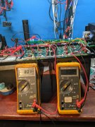
So the AC is wired, and the rectifier is producing correct DC voltage. At this stage no storage caps are connected, I'm simply checking AC and rectifier wiring to ensure it's correct.
Two Flukes have their ground wires connected to the copper bus bar. One Fluke has it's positive wire connected to B+ wire from the rectifier, and reads 80 VDC. The other Fluke has it's positive lead connected to the B- lead from the rectifier, and reads -80 VDC.
This is because these amps use a "center tap transformer". The "center tap" is the transformers secondary wires that connect to the copper bus bar.
Tomorrow I'll show how the AC needs routed, along with routing the DC. Going to crack a Rolling Rock and listen to a album on the big system. Going to listen to Slim Whitman. He claimed he sold more records that Elvis.
 

Attachments

George S.

Veteran and General Yakker
Joined
Feb 18, 2020
Messages
5,036
#68
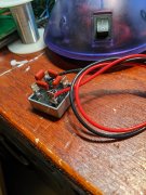
Alright, here we go. Lots of photos for Gene.
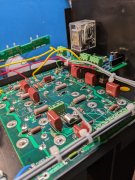
Best to prep the rectifier on the bench. I drill a extra hole in the "dimple" of each lug( Glens idea) and mount the snubber caps there. Add the wiring for the DCP(you'll see the red AC wire in following photos). Building the rectifier while bolted to the cradle is difficult.
 

Attachments

George S.

Veteran and General Yakker
Joined
Feb 18, 2020
Messages
5,036
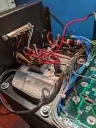
#69
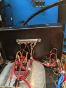
The terminal strip is all AC, power in to the transformer, and power out to the LED board.
The black/ white is Neutral, red/white is Line. The transformers Primary connects to the Neutral and Line.
The transformers secondary powers the LED board, and connects to the rectifier. This is all AC right up to the rectifier. The rectifier converts the AC to DC, and along with the center tap connections to the copper buss bar, we get + and - 80 VDC, as I showed in a earlier photo with the Flukes.
 

Attachments

George S.

Veteran and General Yakker
Joined
Feb 18, 2020
Messages
5,036
#70
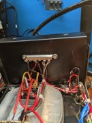
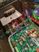
The amp is comprised of AC wiring that we run across the top, and DC wiring we run across the bottom.
In a 400, the AC wiring to the DCP, LED board, and thermal breaker, runs up and around the main fuse holder, then across the top. Don't tuck it tight against the chassis by the back planes. Elevate it to gain distance and minimize noise. Additionally, route it across the cradle so the storage cap fits without pinching wiring
 

Attachments

George S.

Veteran and General Yakker
Joined
Feb 18, 2020
Messages
5,036
#71
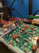
In these photos, all grey wires are grounds and come off the buss bar. There is one black 22 AWG black that is LED board ground.
All blue wires are B-, -80 VDC, all green are B+, 80 VDC.
Note the short grey ground wire coming off the buss bar and going to the stud. This is the star ground. There will be one and only one ground.
Note the short green wire going to the DCP, this is a B+, the DCP requires it, and best to get it off the back plane rather than run a long wire.
The yellow wires are R+L speaker output wires to the DCP, and the small red and white wires beside them at board level drive the meters.
 

Attachments

gene french

Veteran and General Yakker
Joined
Mar 6, 2022
Messages
5,608
Location
guayabo de bagaces, guanacaste, costa rica....
Tagline
music...the healer of souls...
#72
Alright, here we go. Lots of photos for Gene.
Best to prep the rectifier on the bench. I drill a extra hole in the "dimple" of each lug( Glens idea) and mount the snubber caps there. Add the wiring for the DCP(you'll see the red AC wire in following photos). Building the rectifier while bolted to the cradle is difficult.
i heard from joe about the remaining things i needed to accompany the wopl kit....he included the bigger rectifier....so these pics are perfectly timed...
i have a great feeling that it is all about to be shipped!!!!
i am so looking forward to this...
Alright, here we go. Lots of photos for Gene.
Best to prep the rectifier on the bench. I drill a extra hole in the "dimple" of each lug( Glens idea) and mount the snubber caps there. Add the wiring for the DCP(you'll see the red AC wire in following photos). Building the rectifier while bolted to the cradle is difficult.
now i understand snubber caps....joe included those also...
i think i will tell him to double the extra wire....just in case...
 

gene french

Veteran and General Yakker
Joined
Mar 6, 2022
Messages
5,608
Location
guayabo de bagaces, guanacaste, costa rica....
Tagline
music...the healer of souls...
#73
In these photos, all grey wires are grounds and come off the buss bar. There is one black 22 AWG black that is LED board ground.
All blue wires are B-, -80 VDC, all green are B+, 80 VDC.
Note the short grey ground wire coming off the buss bar and going to the stud. This is the star ground. There will be one and only one ground.
Note the short green wire going to the DCP, this is a B+, the DCP requires it, and best to get it off the back plane rather than run a long wire.
The yellow wires are R+L speaker output wires to the DCP, and the small red and white wires beside them at board level drive the meters.
and i bet i dont have taps that small....but not a problem...i will get a small set...mine is mostly bigger stuff....
is it metric or sae???

anything else i need to know about??? prepare for??? put in stock???
 

Gepetto

Administrator
Staff member
Joined
May 15, 2011
Messages
14,087
Location
Sterling, MA
Tagline
Old 'Arn Enthusiast
#75
In these photos, all grey wires are grounds and come off the buss bar. There is one black 22 AWG black that is LED board ground.
All blue wires are B-, -80 VDC, all green are B+, 80 VDC.
Note the short grey ground wire coming off the buss bar and going to the stud. This is the star ground. There will be one and only one ground.
Note the short green wire going to the DCP, this is a B+, the DCP requires it, and best to get it off the back plane rather than run a long wire.
The yellow wires are R+L speaker output wires to the DCP, and the small red and white wires beside them at board level drive the meters.
George
Many put a #4 ring lug on the DCP output and run the meter wires from there. My instructions are written to assume no DCP installed but * footnotes that you can consider taking the meter feeds from the DCP output if desired. I will make the meters absolutely static during power up and down if you go to the DCP.

The note reads as follows:

Note * if you are installing the Watts Abundant DC Protect Device, this wire will route to the input of the DC Protect rather than directly to the speaker output post. Your wire length will be different than shown.

Note ** if you are installing the Watts Abundant DC Protect Device, this wire will route FROM the OUTPUT of the DC Protect Device rather than directly from the backplane board OUT1 pad. Your wire length will be different than shown. For Light Board or Cylon board connections, refer to the instructions provided with those assemblies
 

George S.

Veteran and General Yakker
Joined
Feb 18, 2020
Messages
5,036
#77
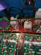
you dont use isopropyl do you???
lol
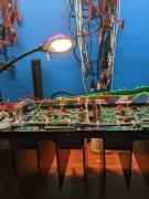
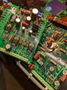
Yep, sure do, 99%. Here's the thing. The boards look absolutely clean and dust free. Not a spot on them. They shine. No visible dust at all on the chassis.
But I'm working under LED lighting and shooting photos with a Google cell phone. This produces images of dirt, dust, and residue that I can't see or remove with 99%. Additionally, the camera picks up reflections on these extra shiny boards that look like debris patches, but just shiny clean board.
Here's something to try. Take a remote control, and point the emitter at your cell phone camera while working the remote. What do you see on the camera you can't see with the naked eye?
 

George S.

Veteran and General Yakker
Joined
Feb 18, 2020
Messages
5,036
#78
George
Many put a #4 ring lug on the DCP output and run the meter wires from there. My instructions are written to assume no DCP installed but * footnotes that you can consider taking the meter feeds from the DCP output if desired. I will make the meters absolutely static during power up and down if you go to the DCP.

The note reads as follows:

Note * if you are installing the Watts Abundant DC Protect Device, this wire will route to the input of the DC Protect rather than directly to the speaker output post. Your wire length will be different than shown.

Note ** if you are installing the Watts Abundant DC Protect Device, this wire will route FROM the OUTPUT of the DC Protect Device rather than directly from the backplane board OUT1 pad. Your wire length will be different than shown. For Light Board or Cylon board connections, refer to the instructions provided with those assemblies
Yes sir. Thank you. Think you had PLP do that on the ones he built for his father
 

gene french

Veteran and General Yakker
Joined
Mar 6, 2022
Messages
5,608
Location
guayabo de bagaces, guanacaste, costa rica....
Tagline
music...the healer of souls...
#79
Yep, sure do, 99%. Here's the thing. The boards look absolutely clean and dust free. Not a spot on them. They shine. No visible dust at all on the chassis.
But I'm working under LED lighting and shooting photos with a Google cell phone. This produces images of dirt, dust, and residue that I can't see or remove with 99%. Additionally, the camera picks up reflections on these extra shiny boards that look like debris patches, but just shiny clean board.
Here's something to try. Take a remote control, and point the emitter at your cell phone camera while working the remote. What do you see on the camera you can't see with the naked eye?
i was picking on you because i saw 3 bottles in one photo....lol
i like your work lamp...i use my frogging/crawfishin head light with magnifiers...
its what i have...lol
guess i should also look for a work lamp on my next amazon order...
and yes i use the cell camera to check the batteries in all of my remotes...
lol...
thanks so much george...i appreciate...
 
Top