After you figure out what is going on in the right channel that is...

You are using an out of date browser. It may not display this or other websites correctly.
You should upgrade or use an alternative browser.
You should upgrade or use an alternative browser.
fitz43's Phase Linear 700 B White Oak Conversion
- Thread starter laatsch55
- Start date
- Joined
- Jan 14, 2011
- Messages
- 75,912
- Location
- Gillette, Wyo.
- Tagline
- Halfbiass...Electron Herder and Backass Woof
Hi Lee
In order to measure the slew rate you will have to have your time base down in the 5 or 10 usec per division and look at a single edge. You will be measuring the time it takes to go from 10 to 90% of the voltage swing and then resolve that into V/usec.
Ok Joe, was going by their example on how to do rise time. Rise time differs that much from slew rate??
- Joined
- Jan 14, 2011
- Messages
- 75,912
- Location
- Gillette, Wyo.
- Tagline
- Halfbiass...Electron Herder and Backass Woof
After you figure out what is going on in the right channel that is...
Yeah, knarly lookin square wave eh??
Rise time is the straight measurement of the time it takes a signal to traverse from 10 to 90 percent or from 90 to 10 percent so the unit is TIME
Slew rate units are Volts/second, sort of the first derivative of rise time and implies a RATE unit.
An analogy that comes to mind is Hours are TIME and Miles Per Hour is RATE.
Hope I am making sense, late here.
Slew rate units are Volts/second, sort of the first derivative of rise time and implies a RATE unit.
An analogy that comes to mind is Hours are TIME and Miles Per Hour is RATE.
Hope I am making sense, late here.
- Joined
- Jan 14, 2011
- Messages
- 75,912
- Location
- Gillette, Wyo.
- Tagline
- Halfbiass...Electron Herder and Backass Woof
Yes you did Joe , Thank You.
fitz43
Veteran and General Yakker
Lee, trying to send you a PM. It's spitting out an error window saying" this page is asking you to confirm that you want to leave - data you have entered may not be saved. <Leave> <stay on page>" when I click on send new message.
fitz43
Veteran and General Yakker
PEBKAC error. PM has been sent.
Got one of those Dennis??
Yes - a Tektronix. One of my test equipment rescues from the rain. It's a little drifty but helps with troubleshooting.
That is cool - I did not know that the Tek scopes could do an FFT.You have one in your new Tek scope Lee. If it has the capabilities that mine does, it has an FFT function in it.
Last edited:
- Joined
- Jan 14, 2011
- Messages
- 75,912
- Location
- Gillette, Wyo.
- Tagline
- Halfbiass...Electron Herder and Backass Woof
Yep the scope and the AP are both FFT capable. I paid wayyyyyyyyyy morte for that AP than I would ever think about paying for a scope.
- Joined
- Jan 14, 2011
- Messages
- 75,912
- Location
- Gillette, Wyo.
- Tagline
- Halfbiass...Electron Herder and Backass Woof
Dennis , did those books help fill in some blanks??
- Joined
- Jan 14, 2011
- Messages
- 75,912
- Location
- Gillette, Wyo.
- Tagline
- Halfbiass...Electron Herder and Backass Woof
PEBKAC error. PM has been sent.
Even jer had to look this one up---- Problem Exists Between Keyboard And Chair
Yes they did and thank you for them. I guess I'll post what I have for numbers. I did SINAD, FR, Clipping (unloaded and loaded) story to follow and a few other tests that I'll need to look back in my notes.Dennis , did those books help fill in some blanks??
Have you tried shielded single conductor wire for the AC runs?
Oh yeah - for those that want to do a little clean up of your photos on the Phoenix server be careful - very careful. I thought I'd delete some photos from my CP Miscellaneous folder and after getting rid of 30 MB or so it occured to me what if this deletes the link from the thread to the photo. I looked - it did - so I've spent several hours locating photos and putting things back together. Thankfully I have the photos I've posted on this site in a couple of folders on my hard drive so I've reconstructed most of the damage. I'll have quite a few modified posts dated today.
I hate it when my name changes to Dumas!
- Joined
- Jan 14, 2011
- Messages
- 75,912
- Location
- Gillette, Wyo.
- Tagline
- Halfbiass...Electron Herder and Backass Woof
Is that a natural progression starting with Dennis?? On Doug's 700B for the DC protect AC feed I ran a twisted , shielded pair.
I've worked a lot with aircraft power and typically we had 28 Vdc or 115 Vac 400 Hz available from the aircraft as a power source. We always use shielded wire for ac power and it wasn't uncommon to shield other signals that were monitored or used for other purposes especially higher frequency stuff. We normally would use the 22759/xx wire for our cable runs and this wire type was commonly used in MIL-C-27500 cable. MIL-C-27500 encompassed a vast array of cable types from single conductor shielded wire to multi wire shielded cable such as a twisted shielded pair.
I know the negative effect that ac can have on signals so by isolating the ac by using distance between it and your signal source is an excellent method of limiting noise and another way of accomplishing this is to use shielded wire - especially if your wire bundle includes both ac power and dc signals.
I know the negative effect that ac can have on signals so by isolating the ac by using distance between it and your signal source is an excellent method of limiting noise and another way of accomplishing this is to use shielded wire - especially if your wire bundle includes both ac power and dc signals.
- Joined
- Jan 14, 2011
- Messages
- 75,912
- Location
- Gillette, Wyo.
- Tagline
- Halfbiass...Electron Herder and Backass Woof
What was the effect of having 120 AC @ 400 hz as opposed to 60HZ.?? Had 400Hz hum instead of 60??
- Joined
- Jan 14, 2011
- Messages
- 75,912
- Location
- Gillette, Wyo.
- Tagline
- Halfbiass...Electron Herder and Backass Woof
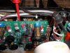
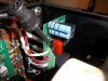
Doug, I have changed out the Zoebel network on Don's board. After chatting with Joe, this will be an improvement, So it is done. A final bias setting and I'll put the top and bottom covers on it . As soon as the cabbage case gets here it'll be gone the next morning.
Attachments
Doug, I have changed out the Zoebel network on Don's board. After chatting with Joe, this will be an improvement, So it is done. A final bias setting and I'll put the top and bottom covers on it . As soon as the cabbage case gets here it'll be gone the next morning.
So what's the wattage of those two 10 Ohm resistors?? Nice job on the install.
My 400 has two 12 Ohm resistors in parallel - so should there be a difference between the 700 and 400?
- Joined
- Jan 14, 2011
- Messages
- 75,912
- Location
- Gillette, Wyo.
- Tagline
- Halfbiass...Electron Herder and Backass Woof
No, Dennis the same Zoebel, should be 2 10 ohmers, or a large 5 ohmer. the 10's I put in are 5 watters. I also replaced the cap with a .1uf 250 volt polypro. Gotta say, it does sound better. More definition. Yeah, had to get tricky to get em to fit.
No, Dennis the same Zoebel, should be 2 10 ohmers, or a large 5 ohmer. the 10's I put in are 5 watters. I also replaced the cap with a .1uf 250 volt polypro. Gotta say, it does sound better. More definition. Yeah, had to get tricky to get em to fit.
Got it. I'll need to update my DC protect board. I haven't removed the wire wound resistors yet but it seems that that the thru-hole diameter on the PCB is on the smallish side for a five or ten watt resistor. Yeah - it's tough making something large fit a small hole. I like how you worded that though.