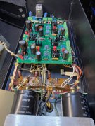
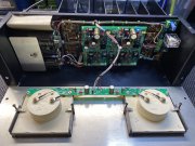
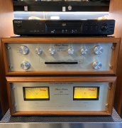
First PL-400 Restoration

Switchcraft red and white gold plated off Mouser are direct replacements and upgrade from original which are not gold plated
Thanks Joe - I'm on it!

Not sure if Phoenix allows direct links(?); do these Mouser parts look right? 502-BPJF01AUX (black) and 502-BPJF02AUX (red)
 
Last edited:
I looked these up. If I read the data sheet correctly, the body is gold plated but the tip is nickle and so is the nut and washer. Did I miss something?
 
Body, nut and tip connection are gold plated. The solder ring lug that goes around the body is nickel plated but that is not used in the original PL application as the copper plate does that
 
All done! Light board in, warm white LEDs this time, triple checked bias, stuck in a case for now until I start pushing it. Thanks to all who helped me along! Those White Oak boards and supplies were absolutely perfect. I'm gonna hook up some better speakers to this and see what it can do. With some test speakers and 1/3 volume on the preamp, it's pretty dang loud, lol. Sounds great though.

IMG_4694.jpegIMG_4703.jpeg
 
Looking forward to getting mine back up and running one of these days.... Soon.

P.S. and the 700II too!
 
All done! Light board in, warm white LEDs this time, triple checked bias, stuck in a case for now until I start pushing it. Thanks to all who helped me along! Those White Oak boards and supplies were absolutely perfect. I'm gonna hook up some better speakers to this and see what it can do. With some test speakers and 1/3 volume on the preamp, it's pretty dang loud, lol. Sounds great though.

View attachment 40366View attachment 40367

One finishing touch Dave. You will notice that the light board has a pair of holes adjacent to the 5 hole diagonal wire connection pattern. These holes are there to lace a cable tie through and pull the wire harness down on the board to provide strain relief for the solder connections that you accomplished very nicely. Keeps those from flexing and breaking at the solder joint.

20131201_iPhone 015.JPG
 
One finishing touch Dave. You will notice that the light board has a pair of holes adjacent to the 5 hole diagonal wire connection pattern. These holes are there to lace a cable tie through and pull the wire harness down on the board to provide strain relief for the solder connections that you accomplished very nicely. Keeps those from flexing and breaking at the solder joint.

Thanks Joe ! The OEM board had wire 1 completely severed; wire 2 was hanging on by a few strands. Will get one on there today; great design! :)
 
Back
Top