e30m3mon
Chief Journeyman
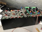
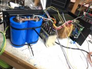
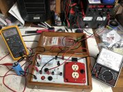
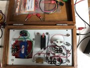
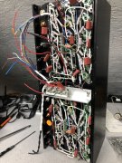
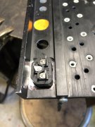
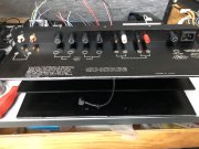
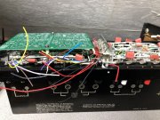
Been a while since I have posted any updates on the D500 rebuild project I started a couple months ago, but to date it has been a matter of getting the chassis prepared for some circuit enhancements Glen has been developing for this platform, as well as getting the backplane he built for me installed back onto my rear chassis/heat sink. Also had to modify the heat sink to accommodate an IEC connector and the gold plated input/output jacks required additional clearance to ensure no conductors are touching the chassis metal. Next I will be starting on the WOAD Control board and some changes Glen and Joe have developed.
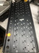
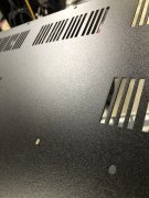
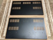
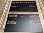
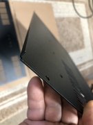
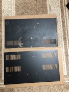
In the meantime, my amp did not arrive with a top cover and the bottom cover was pretty well beat up ... simply repainting would not work. Bondo might have fixed some of the damage, but that was not an option either. Glen provided me a couple pics of his top cover ... which I went to a local fabrication shop and had several sets of tops&bottoms made up. They are laser-cut from 18GA steel, far heavier than the original 20GA, which might actually help with quieting the massive transformer's hum. I then had them powder coated with matte-black textured finish. They are very attractive and fit perfectly with all chassis holes in the correct place and 1/4" turn-up at the front panel edge. The bottom panels have 2 sets of holes to accommodate the relay bracket which apparently had 2 potential mounting positions. I had sent a couple sets to Glen for test fitting ... he confirmed these fit perfectly and look great! There is a comparison pic between the original bottom panel and the new one - I added more vents on the bottom as well as the top, compared to the originals.
I'll be selling the remaining tops&bottoms at $110 per set, plus $25-27 for USPS Large Flat Rate Shipping. Pics attached for reference.
Al
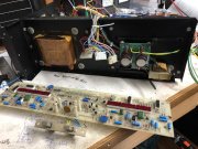
Attachments
-
 67884777203__7B1CE06A-9C26-461C-A33C-7E9142D7BAF4 Large.jpeg243.2 KB · Views: 31
 -
 68031810597__090BCB63-32B7-46EB-83D2-4DD8E2EC9A98 Large.jpeg394.4 KB · Views: 30
 -
 IMG_7209 Large.jpeg209.7 KB · Views: 30
 -
 IMG_7276 Large.jpeg268.2 KB · Views: 29
 -
 68031768586__C0CBE332-CB3B-490A-BA03-037D095208FF Large.jpeg344.6 KB · Views: 29
 -
 IMG_7097 Large.jpeg422.5 KB · Views: 29
 -
 IMG_7352 Large.jpeg400.9 KB · Views: 24
 -
 IMG_7353 Large.jpeg417.4 KB · Views: 27
 -
 IMG_7354 Large.jpeg143.6 KB · Views: 27
 -
 IMG_7355 Large.jpeg350.6 KB · Views: 26
Last edited:


")