You are using an out of date browser. It may not display this or other websites correctly.
You should upgrade or use an alternative browser.
You should upgrade or use an alternative browser.
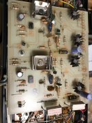
Control board
- Thread starter FredR
- Start date
- Joined
- Jan 14, 2011
- Messages
- 75,921
- Location
- Gillette, Wyo.
- Tagline
- Halfbiass...Electron Herder and Backass Woof
Not a whole lotta parts on there...
Not a whole lotta parts on there...
Hard working bean counters Lee
oldphaser
Chief Journeyman
- Joined
- Sep 8, 2012
- Messages
- 869
You should replace as a matter of course the (2) Rockwood brand 7.5K ohm 5 watt resistors and the (2) 7.5K 2 watt resistors. The Rockwood brand were known to have a higher than normal failure rate. (Phase Linear also used a TRW PW5 series later on that was much more reliable.) The 7.5K ohm 2 watt resistors will also go up in value with age, heat, humidity, etc. The 2.7K 1/3rd watt resistors next to the 7.5K 2 watt resistors should be replaced with 1/2 watt at the very least.
Ed
Ed
- Joined
- Jan 14, 2011
- Messages
- 75,921
- Location
- Gillette, Wyo.
- Tagline
- Halfbiass...Electron Herder and Backass Woof
mlucitt
Veteran and General Yakker
Probably the cleanest board and amp I have ever seen of that era. Looks like a museum piece.
wattsabundant
Chief Journeyman
I've seen the 7.5k/2W resistor, that Ed mentions, fail several times. I automatically replace it. C111 (100uf/6.3v) fails frequently. C101 (47uf/100v) faills less frequently. I've seen C304 (4.7uf/35V) on the display board fail a lot. The same cap is used elsewhere on the board, but doesn't seem to fail. I don't know why. If any work is being done on the display I would suggest replacing all of the electrolytics.
oldphaser
Chief Journeyman
- Joined
- Sep 8, 2012
- Messages
- 869
I've seen the 7.5k/2W resistor, that Ed mentions, fail several times. I automatically replace it. C111 (100uf/6.3v) fails frequently. C101 (47uf/100v) faills less frequently. I've seen C304 (4.7uf/35V) on the display board fail a lot. The same cap is used elsewhere on the board, but doesn't seem to fail. I don't know why. If any work is being done on the display I would suggest replacing all of the electrolytics.
C111/211 (100uf/6.3V or 100uF 10V) usually only becomes an issue after the amp has had a failure (i.e. blown output transistors, etc.) However, it could be replaced as a matter of course with a higher voltage rating (i.e. 35V). Replacing these caps with a higher value (i.e. 470uF) will lower the frequency response (-1dB point when measured at 1W) from 12Hz down to around 4 to 5Hz and phase as well. In general, I don't increase the nominal value of this cap.
C101/201 (47uF/100V) failures are not very common. The Nichicon's Phase Linear used were perhaps the best.
I have been experiencing more failures of caps on the display board the last few years. So replacing them all is not a bad idea for someone who doesn't have the ability to check for value, leakage or ESR.
oldphaser
Chief Journeyman
- Joined
- Sep 8, 2012
- Messages
- 869
Fred,
Although your original post centered around the PL-36 pc board.....
Perhaps I should also address the other kinds of issues that can come up with a Phase Linear 400 series II.
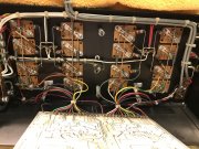
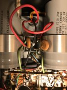
Phase Linear used a variety of power supply capacitor manufacturer's and about the time the fully comp amps came out they used some FAO brand which had a higher than normal failure rate. By the way, Carver also used the same brand in his C-500 amps. If you see any FAO brand they should automatically be replaced.
You may also want to measure the value of the 10 ohm resistors (R128 and R180) located in the output stage. Most amplifiers had carbon composition type which are going up in value with age, etc. Ideally they should be 10 ohms which makes adjusting the bias a little easier. However they are usually a 10% tolerance part and the "DC voltage drop" will measure differently between the (2) resistors when the resistors are not closely matched in there values. I am beginning to replace these as a matter of course as they have caused me some grief.
Additionally, there was a low distortion mod that Phase Linear first used on the 300 series II amplifiers (see R118 and C108 on the 300 II schematic) that they eventually used on some later 700 series II fully comp amp PL-36 pc boards. This involves removing the 120pF cap (C106/C206) that is in series with the 12K ohm resistor (R128/R129) next to Q106/Q206 and installing a 56pF cap in parallel with the 12K ohm resistor. This will greatly reduce the classic crossover notch and THD levels (particularly at lower volume levels) that you see with many Phase Linear amps (at 1kHz, 1 watt, 8 ohms). In which case the bias should be adjusted to approximately 385mV (which also works better when the 10 ohm resistors are nearer the nominal value of 10 ohms).
I have created other threads in the past concerning RCA jacks and volume pots:
https://forums.phxaudiotape.com/thr...t-3501fr-phase-linear-amplifiers-others.8319/
https://forums.phxaudiotape.com/threads/so-what-does-the-inside-of-your-pot-look-like.8306/
Ed
Last edited:
Quickcarl
New Around These Parts
Thanks OldPhaser for splaining the details for replacing the caps (such as the 100uf/6.3V ) and and what it does for the lower frequency response of the amp. Of course i am applying this to the D and Dual 500's, so the numbers are a little different. Learn something new everyday.
Quickcarl
New Around These Parts
The amp/board in FredR's picture.. Did that come out of a clean room or something? Never seen one that clean.
mlucitt
Veteran and General Yakker
See post #6. Funny how we all think alike sometimes...The amp/board in FredR's picture.. Did that come out of a clean room or something? Never seen one that clean.
oldphaser
Chief Journeyman
- Joined
- Sep 8, 2012
- Messages
- 869
Thanks OldPhaser for splaining the details for replacing the caps (such as the 100uf/6.3V ) and and what it does for the lower frequency response of the amp. Of course i am applying this to the D and Dual 500's, so the numbers are a little different. Learn something new everyday.
If you intend to use the 470uF capacitor to lower the frequency response in a Phase Linear Dual 500/D-500 or a Phase Linear 700, 700B or 700 series II amp with Don's relay board in it you will not be able to realize full output at 5Hz because the relay board will trip when driven at 5Hz at approximately 25-28 volts in one channel and approximately 33-36 volts in the other channel. The difference is only slight whether the amplifier is unloaded or loaded (@ 8 ohms).
NOTE: Don's 700 relay board is pretty much a clone of the relay circuit in a Dual 500/D-500 and performs similarly.
Ed
- Joined
- Jan 14, 2011
- Messages
- 75,921
- Location
- Gillette, Wyo.
- Tagline
- Halfbiass...Electron Herder and Backass Woof
Pristine is what that is!!
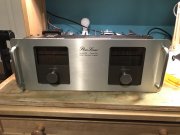
Background is I bought the amp off ebay 2 or 3 years ago as a WOPL conversion. Once I got it and saw the condition I decided to keep it as original. (BTW, did not do any cleaning at all before pics) With necessary upgrades like DC protect, etc. Particularly since it is factory complementary. Just took me awhile to get around to it.
Only issues are a noisy volume pot in the left channel and the meters power up with a red dot but do not respond to input. Just sit there. I'll look at it but probably replace with Joe's board for longevity.
Only issues are a noisy volume pot in the left channel and the meters power up with a red dot but do not respond to input. Just sit there. I'll look at it but probably replace with Joe's board for longevity.
Probably the cleanest board and amp I have ever seen of that era. Looks like a museum piece.
Last edited:
Really appreciate it Ed! Especially the extra effort you put in the post. I've already got the parts to replace the power supply capacitors, rectifier and snubbers. (Ha, spell check wanted to replace that with rubbers). Have already replaced the NEC parts with ON 95/96. POTS are on the replacement list as well. Once all this is done I'll test it on a fused speaker wire on low end speakers. If all is well I'll add DC protect, new RCAs, and convert to star ground. Fred.
I made a few edits to my previous post.
Last edited:
Just got lucky.
The amp/board in FredR's picture.. Did that come out of a clean room or something? Never seen one that clean.

