You are using an out of date browser. It may not display this or other websites correctly.
You should upgrade or use an alternative browser.
You should upgrade or use an alternative browser.
Control board
- Thread starter FredR
- Start date
mlucitt
Veteran and General Yakker
Ed said Quote "You may also want to measure the value of the 10 ohm resistors (R128 and R180) located in the output stage. Most amplifiers had carbon composition type which are going up in value with age, etc. Ideally they should be 10 ohms which makes adjusting the bias a little easier. However they are usually a 10% tolerance part and the "DC voltage drop" will measure differently between the (2) resistors when the resistors are not closely matched in there values. I am beginning to replace these as a matter of course as they have caused me some grief."
Are these 1/2W resistors from Mouser a good choice to replace the 10 Ohm bias resistors in PL amps?
https://www.mouser.com/ProductDetail/660-MF1-2CCT52R10R0F
Are these 1/2W resistors from Mouser a good choice to replace the 10 Ohm bias resistors in PL amps?
https://www.mouser.com/ProductDetail/660-MF1-2CCT52R10R0F
I have a request in with Ed for all the part numbers if he has them handy.
Ed said Quote "You may also want to measure the value of the 10 ohm resistors (R128 and R180) located in the output stage. Most amplifiers had carbon composition type which are going up in value with age, etc. Ideally they should be 10 ohms which makes adjusting the bias a little easier. However they are usually a 10% tolerance part and the "DC voltage drop" will measure differently between the (2) resistors when the resistors are not closely matched in there values. I am beginning to replace these as a matter of course as they have caused me some grief."
Are these 1/2W resistors from Mouser a good choice to replace the 10 Ohm bias resistors in PL amps?
https://www.mouser.com/ProductDetail/660-MF1-2CCT52R10R0F
grapplesaw
Veteran and General Yakker
I upgrade these to 1 watt Dale
They are high heat 1% metal film. Do not get much better than these. This resistor failure has caused all sorts of Phase linear bias runaway problem so why not be safe.
Mouser # 71-CPF110R000FKEE6
They
They are high heat 1% metal film. Do not get much better than these. This resistor failure has caused all sorts of Phase linear bias runaway problem so why not be safe.
Mouser # 71-CPF110R000FKEE6
They
mlucitt
Veteran and General Yakker
Those go to 446 degrees F! If my WOPL backplane gets that hot it is because the house is burning down...I upgrade these to 1 watt Dale
They are high heat 1% metal film. Do not get much better than these. This resistor failure has caused all sorts of Phase linear bias runaway problem so why not be safe.
Mouser # 71-CPF110R000FKEE6
They
I like that they say "Flameproof".
Those are what I use. Not low cost but very good. Tiny too.
mlucitt
Veteran and General Yakker
Those are what I use. Not low cost but very good. Tiny too.
I would like them more if they were 50ppm/C instead of 100ppm/C, still low, and probably not an issue. Calculated resistance values from temperature coefficient of resistance (TCR) at the extremes would be 10.295 to 9.7050 Ohms not including the rating tolerance.
Hi Mark
Then use the CMF6010R000FHEK which has a 50ppm/c tempco
Typically you will see a temp swing of no more than 45C at the control board which will induce a drift of ~+/-4.5 milliohms in a 100ppm resistor.
Then use the CMF6010R000FHEK which has a 50ppm/c tempco
Typically you will see a temp swing of no more than 45C at the control board which will induce a drift of ~+/-4.5 milliohms in a 100ppm resistor.
mlucitt
Veteran and General Yakker
I guess I was confused. If the temp swing is no more than 45C, then why spec a resistor to 230C?
Sorry, it is taking me awhile to get back into this fantastic hobby after being away for awhile. There have been some improvements in technology over the past five years. Some of the parts I previously used are no longer available. I just want to use the best engineered parts, consistent with availability and value, for the designed functionality. I like to hear what parts & techniques other forum members are using, and I like to do independent research. Please excuse me if I go too far afield, sometimes I find myself talking to the only person in the room, me.
Sorry, it is taking me awhile to get back into this fantastic hobby after being away for awhile. There have been some improvements in technology over the past five years. Some of the parts I previously used are no longer available. I just want to use the best engineered parts, consistent with availability and value, for the designed functionality. I like to hear what parts & techniques other forum members are using, and I like to do independent research. Please excuse me if I go too far afield, sometimes I find myself talking to the only person in the room, me.
- Joined
- Jan 14, 2011
- Messages
- 75,849
- Location
- Gillette, Wyo.
- Tagline
- Halfbiass...Electron Herder and Backass Woof
But I read everything...
I guess I was confused. If the temp swing is no more than 45C, then why spec a resistor to 230C?
Sorry, it is taking me awhile to get back into this fantastic hobby after being away for awhile. There have been some improvements in technology over the past five years. Some of the parts I previously used are no longer available. I just want to use the best engineered parts, consistent with availability and value, for the designed functionality. I like to hear what parts & techniques other forum members are using, and I like to do independent research. Please excuse me if I go too far afield, sometimes I find myself talking to the only person in the room, me.
Hi Mark
They rate these resistors for applications much more severe than we use them in. These resistors are loafing with a huge amount of derating in our typical application. For the bias application, the dissipation is ~13mW but the resistors are rated for 1000mW which means that our derating factor is 98.7%. Huge.
On tempco, if we see a 45C swing inside the chassis then something is seriously wrong (like all the air vents have been blocked up. So that 45C swing we talked about really represents a corner case.
mlucitt
Veteran and General Yakker
Sometimes I think of myself as George Bailey, "...this business of nickels and dimes and spending all your life trying to save three cents on a length of pipe."
I see how the bias resister function could be accomplished with a wet Popsicle stick, but we love these amplifiers and simply want the best, so we derate or over-rate the specifications of the resistors (and other parts) to some degree that makes engineering sense. How much engineering sense and associated cost is a subjective decision. I myself enjoy the hunt for the best parts that I can find, to effectively do the job at the least cost, if cost is a factor; and I think it should be while some may disagree. I would say no to $600 interconnects when the $24 Radio Shack cables perform just as well, subjectively, to me.
I see how the bias resister function could be accomplished with a wet Popsicle stick, but we love these amplifiers and simply want the best, so we derate or over-rate the specifications of the resistors (and other parts) to some degree that makes engineering sense. How much engineering sense and associated cost is a subjective decision. I myself enjoy the hunt for the best parts that I can find, to effectively do the job at the least cost, if cost is a factor; and I think it should be while some may disagree. I would say no to $600 interconnects when the $24 Radio Shack cables perform just as well, subjectively, to me.
mlucitt
Veteran and General Yakker
Which resistors do you guys recommend for the PL400 output transistor emitters? The original ones are .22 Ohm 2 Watt carbon composition, as you know.
Which resistors do you guys recommend for the PL400 output transistor emitters? The original ones are .22 Ohm 2 Watt carbon composition, as you know.
Hi Mark
The original 0.22 are wirewound, not CC. I recommend MOS in all emitter applications as they are not inductive. We use the 0.33 3W 2% which are recommended for the WO application as the release notes discuss.
mlucitt
Veteran and General Yakker
Hi Mark
The original 0.22 are wirewound, not CC. I recommend MOS in all emitter applications as they are not inductive. We use the 0.33 3W 2% which are recommended for the WO application as the release notes discuss.
Joe, thank you for clarifying. The side note part of the release notes mention the .33 ohm emitter resistor, but I thought that only applied to the backplane kits. I ignored that because I was not using the kits this time around. Re-reading the note, I see it is a general, and not a specific, change in the application of the specs of the emitter resistors and the base-emitter resistors for the pre-drivers.
Are these the ones from Mouser that you use?
660-MOSX3CT631RR33G
Last edited:
Looks right MarkJoe, thank you for clarifying. The side note part of the release notes mention the .33 ohm emitter resistor, but I thought that only applied to the backplane kits. I ignored that because I was not using the kits this time around. Re-reading the note, I see it is a general, and not a specific, change in the application of the specs of the emitter resistors and the base-emitter resistors for the pre-drivers.
Are these the ones from Mouser that you use?
660-MOSX3CT631RR33G
mlucitt
Veteran and General Yakker
Just ordered 14 of them from Mouser.
MusicSteve
Journeyman
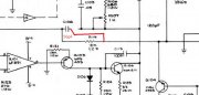
Ed Is this correct I'm little confused.Fred,
700 series II fully comp amp PL-36 pc boards. This involves removing the 120pF cap (C106/C206) that is in series with the 12K ohm resistor (R128/R129) next to Q106/Q206 and installing a 56pF cap in parallel with the 12K ohm resistor. This will greatly reduce the classic crossover notch and THD levels (particularly at lower volume levels) that you see with many Phase Linear amps (at 1kHz, 1 watt, 8 ohms). In which case the bias should be adjusted to approximately 385mV (which also works better when the 10 ohm resistors are nearer the nominal value of 10 ohms).
Ed
Converted the text to this as I read it, w ***
700 series II fully comp amp PL-36 pc boards.
1. This involves removing the 120pF cap (C106/C206) that is in series with the 12K ohm resistor (R128/R129) next to Q106/Q206 ******** R119/R219************************
2. and installing a 56pF cap in parallel with the 12K ohm resistor. This will greatly reduce the classic crossover notch and THD levels (particularly at lower volume levels) that you see with many Phase Linear amps (at 1kHz, 1 watt, 8 ohms). In which case the bias should be adjusted to approximately ********************Add Jumper?*************
3. 385mV (which also works better when the 10 ohm resistors are nearer the nominal value of 10 ohms).
I have made 2-drawing and this is the second one which I think is correct? (I love Drawing not Text)
Thanks anybody who has done this?
Attachments

I don't think so...Ed Is this correct I'm little confused.
Converted the text to this as I read it, w ***
700 series II fully comp amp PL-36 pc boards.
1. This involves removing the 120pF cap (C106/C206) that is in series with the 12K ohm resistor (R128/R129) next to Q106/Q206 ******** R119/R219************************
2. and installing a 56pF cap in parallel with the 12K ohm resistor. This will greatly reduce the classic crossover notch and THD levels (particularly at lower volume levels) that you see with many Phase Linear amps (at 1kHz, 1 watt, 8 ohms). In which case the bias should be adjusted to approximately ********************Add Jumper?*************
3. 385mV (which also works better when the 10 ohm resistors are nearer the nominal value of 10 ohms).
I have made 2-drawing and this is the second one which I think is correct? (I love Drawing not Text)
Thanks anybody who has done this?