Bridged Phase Linear series ll

grapplesaw

Veteran and General Yakker
Joined
Aug 13, 2014
Messages
2,786
Location
Vancouver
Tagline
---
I will start my new build thread Of a stereo / mono 400

This build was started in concept last spring. There is much debate as it being a good idea to build this configuration or not. Forseen problems of high heat and reduced sound quality are to be concerned about.

After a push from Lee and Perry to build some monster monos I set out to build this mini mono before going all in.

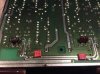
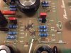
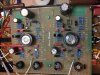
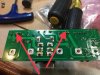
It is a simple enough concept and with the help from THD+N and a board he made a few years ago that I have been holding onto.

The design for mono setup is basically having one inverted channel with one conventional channel and connecting the two hot outs to the speakers.

The bridge of the two channels does two things. First it addes the two channels into one. But doing this when using a 8 ohm load it instead sees it as a 4 ohm load a again amplifies the power output. So we will see what tha is during testing. THD will also be interesting to see if ther is much change from the un bridged state of the amp. Other issue are the actual rail voltage vs that seen by the drivers.

I will try some things in the build that may seam a little over the top but who cares.
 
Here is what makes it work

The control board has a dual opamp in each channel. This can make a inverted output. Other ways to invert the channels is running through a centre tap transformer on the inputs.

The amp amp will remain useful as a stereo amp if wanted. The only thing that needs to be done is pug a mono speaker into the two hot output binding posts. There is no ground as such for mono.

the board is a basic PL36 with some nice additions of decoupling caps, power supply capsand the dual opamp setup. It also has extra heavy copper traces.
 
Pl36 v2 board

I changed the board to go full complimentary. X mark removed components not needed. The white wire is needed to supply fused neg voltage to output trans collector.

The board has high pass filter mounting point if wanted, I am bypassing this.
 

Attachments

  • 08447A18-44AC-48ED-8B08-C5DD80EDE43D.jpg
    08447A18-44AC-48ED-8B08-C5DD80EDE43D.jpg
    19.9 KB · Views: 36
  • B432D84D-6E8A-4E78-8D99-94C9112B7647.jpg
    B432D84D-6E8A-4E78-8D99-94C9112B7647.jpg
    19.7 KB · Views: 36
  • 94076E5B-CE41-44B4-87FC-ECCEA96B93EA.jpg
    94076E5B-CE41-44B4-87FC-ECCEA96B93EA.jpg
    20.3 KB · Views: 61
Starting with the chassis

I modified the chassic to add thermo switch and fan plug in center of backplate
before and after shots
 

Attachments

  • EC959BE5-D1F7-47BC-BFE0-BB9D19B70830.jpg
    EC959BE5-D1F7-47BC-BFE0-BB9D19B70830.jpg
    12.5 KB · Views: 37
  • 09017007-6A66-4FAA-ADC1-82AD6ADFFA4C.jpg
    09017007-6A66-4FAA-ADC1-82AD6ADFFA4C.jpg
    16.4 KB · Views: 37
  • 2E194300-0337-45D5-B842-F0D9E01F25BD.jpg
    2E194300-0337-45D5-B842-F0D9E01F25BD.jpg
    11.1 KB · Views: 36
  • EB2A8D49-1FB2-4956-A8A7-528E55692C24.jpg
    EB2A8D49-1FB2-4956-A8A7-528E55692C24.jpg
    21.3 KB · Views: 46
Last edited:
Yeppers, you do get into those projects bud.....super cool...
 
I upgraded Don’s DCP board with 3 watt resistors 450 volt Zobel caps and meter terminals on board. Used 3/8†stainless standoff’s to get a little more clearance from the backplate.
 

Attachments

  • FE26DC89-0C35-4A5F-801D-CE11B144122B.jpg
    FE26DC89-0C35-4A5F-801D-CE11B144122B.jpg
    20.7 KB · Views: 44
  • 27EDEAD7-0C65-4024-A246-3CA5C890C377.jpg
    27EDEAD7-0C65-4024-A246-3CA5C890C377.jpg
    20.1 KB · Views: 40
  • 536E0885-0579-4970-8088-5A0E796CC93A.jpg
    536E0885-0579-4970-8088-5A0E796CC93A.jpg
    9.9 KB · Views: 40
Powercaps and ac terminals

So we need some juice to amp this thing up ,right? I added one of Joe’s cap kits to get 16,000uf per rail. They are mounted to side wall of chassic. 50 amp Bridge rectifier and 1/2watt thermal reset fuse for meter supply.
 

Attachments

  • BEF8CC25-E953-4C45-AF82-28AD93E491A5.jpg
    BEF8CC25-E953-4C45-AF82-28AD93E491A5.jpg
    18.7 KB · Views: 37
  • 39BC01CB-61A1-4DFC-BB83-15E612FA7F11.jpg
    39BC01CB-61A1-4DFC-BB83-15E612FA7F11.jpg
    22.6 KB · Views: 37
  • 9D40DA48-7198-44D0-A4A6-9509AF9EC7D6.jpg
    9D40DA48-7198-44D0-A4A6-9509AF9EC7D6.jpg
    20.7 KB · Views: 36
Backplates mod

So I did not have a set of Joe’s Backplates so I put in a few changes of my own. Removed the ferrite beads and added a few more versions caps to power rails. One watt bias resistors.
 

Attachments

  • 6305C101-42EF-4AA9-AC3D-2871C28B539A.jpg
    6305C101-42EF-4AA9-AC3D-2871C28B539A.jpg
    20.5 KB · Views: 33
  • 59759C1D-620E-4F89-A81E-39FA83057811.jpg
    59759C1D-620E-4F89-A81E-39FA83057811.jpg
    20.6 KB · Views: 31
Bias transistors to be added along with a little tidying up and the main section will be done. Front panel left and may have something up
my sleeve there.

Well that is it for the next 10 days or so.
More to come stay tuned :cheers:
 

Attachments

  • 1CBCCF1C-C24A-4257-957E-CA4BC05DCC95.jpg
    1CBCCF1C-C24A-4257-957E-CA4BC05DCC95.jpg
    21 KB · Views: 39
  • 3C40194A-972B-48AA-BBA2-51556F5B0905.jpg
    3C40194A-972B-48AA-BBA2-51556F5B0905.jpg
    22.3 KB · Views: 34
Last edited:
Why 2 thermoswitches?
One for high heat shut down and the other One operates the plug for the fan. Closes at 30’C to turn on the fan. I have always wanted to put this in the 700’s but never got around to it.
 

Attachments

  • 97105F79-91FD-45A7-B9AD-F0892B7E1729.jpg
    97105F79-91FD-45A7-B9AD-F0892B7E1729.jpg
    12.5 KB · Views: 27
Last edited:
There is much debate as it being a good idea to build this configuration or not. Foreseen problems of high heat and reduced sound quality are to be concerned about.

Solid state amps have been built with bridging options for a long time. There are different ways to bridge an amp, and depending on the method used, DC offset may be affected. Distortion will usually rise slightly because you are driving a lower load as seen by the amp. With the configuration you are using Glen, DC offset will not be an issue.

If you plan on driving the 400 hard, you may need a fan to help keep the heat sink cool. The 400 bridged should put out over 700 Watts RMS (>0.25% THD+N, if I remember correctly) into an 8 Ohm load.

Other issue are the actual rail voltage vs that seen by the drivers.
Not sure I follow you here. Please clarify.
 
Solid state amps have been built with bridging options for a long time. There are different ways to bridge an amp, and depending on the method used, DC offset may be affected. Distortion will usually rise slightly because you are driving a lower load as seen by the amp. With the configuration you are using Glen, DC offset will not be an issue.

If you plan on driving the 400 hard, you may need a fan to help keep the heat sink cool. The 400 bridged should put out over 700 Watts RMS (>0.25% THD+N, if I remember correctly) into an 8 Ohm load.


Not sure I follow you here. Please clarify.

I have returned to this project and have measured output. So with same input level we now have double voltage out. This is because two channels have joined together.
THD+N is about double as non bridged at equal voltage output but the bridge set up can put out double The voltage.

I plan on using this for a bass driver and at lower Hz the THD+N dramatically lower
so we have a winner. A little heavy testing will confirm.
 
I am a bit confused, Lee told me 400 and 700s could not be bridged BUT you could just use one channel a get a little bit more power??
 
nO, i SAID THEY COULD BE BRIDGED BUT IT WOULD BE A BAD IDEA.. damn caps lock....Ya can't drive a 4 ohm load, distortion rises, BUT, with Glen doing this we will know for sure...
 

Attachments

  • B858EFCC-5AAC-4CD7-A164-C47D199626BA.jpg
    B858EFCC-5AAC-4CD7-A164-C47D199626BA.jpg
    20.3 KB · Views: 31
  • 17699698-3A1D-4EA8-B8CF-C3B98F11B7BD.jpg
    17699698-3A1D-4EA8-B8CF-C3B98F11B7BD.jpg
    19.7 KB · Views: 31
  • 420B57B0-32E6-4640-914F-E04074CC0529.jpg
    420B57B0-32E6-4640-914F-E04074CC0529.jpg
    19.7 KB · Views: 30
Last edited:
Back
Top