Barn Find PL400

dcmeigs

New Around These Parts
Joined
Apr 6, 2024
Messages
47
#22
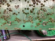
did you remove/ reinstall outputs??
if so...you may have over tightened ..and shorted collector to chassis
the 120 watt bulb will only allow 1 amp to pass...your fuses are 5 amp....
but without dbt...you would have blown fuses
Thanks Gene, but if I start the amp without the right speaker connected, wait for it to come up and then connect that right speaker, then it will play well without issue. It’s only when it is started under load that this happens.
 

George S.

Veteran and General Yakker
Joined
Feb 18, 2020
Messages
4,603
#23
Those are across C6? My board is the 14b. 1N4181 okay?
I don't know. I gutted each PL400 and 700 amp, never even plugged them in, then built them with all the WOPL goodies.
If you do a forum search for latch up, you'll find quite a bit of info.
Somewhere in there is the info for adding diodes.
Think it has to do with capacitor charging rates or capacity.
 

laatsch55

Administrator,
Staff member
Joined
Jan 14, 2011
Messages
74,281
Location
Gillette, Wyo.
Tagline
Halfbiass...Electron Herder and Backass Woof
#24
Have you had a meter on the right speaker posts bringing it up to what its passing?
 

laatsch55

Administrator,
Staff member
Joined
Jan 14, 2011
Messages
74,281
Location
Gillette, Wyo.
Tagline
Halfbiass...Electron Herder and Backass Woof
#25
Run a pair if 1N4148's back to back , reversed to each other, then solder on the trace side ACCROSS the leads of C6 . Should be 100 uf cap. To get a much better low frequency response, replace that 100 with a 470 if cap..audio cap if possible, because that one does affect ghe signal directly.
 

dcmeigs

New Around These Parts
Joined
Apr 6, 2024
Messages
47
#27
Thanks Laatsch55. I installed a couple of reversed parallel diodes across the right channel C6 without effect. I’m getting a 6v dc offset while it’s in the upset mode. Interesting thing is that the offset is on both channels even though it’s the right channel that seems sensitive to the speaker load. Exploring that further the rail voltages are about +10 and - 24. Another thing interesting, if I double clutch, it Will come out of its upset condition. By that I mean switching it on for a few seconds and then cutting mains briefly. I’m at a loss.

I am using 100uf for C6.

Edit: What I’m thinking is that high current draw from the charging caps is causing the rail voltages to not come up fast enough. Once I get the caps half charged and reset the amp by briefly cutting the power, then the caps fully charge and everything is fine. I’m wondering if it’s the dim bulb that’s causing the problem. I don’t understand the protection circuit well enough to think this through.
 
Last edited:

gene french

Veteran and General Yakker
Joined
Mar 6, 2022
Messages
5,259
Location
guayabo de bagaces, guanacaste, costa rica....
Tagline
music...the healer of souls...
#30
you cant set bias and offset while on dbt...they will not be correct...
rail voltage will be down too...but not that low ...
without dcp board...i would be afraid to run without dbt...you might want the wo cap upgrade ...almost all do that whether they restore original or upgrade wopl...please run junker speakers until its sorted out ... ive blown a few too....
 

dcmeigs

New Around These Parts
Joined
Apr 6, 2024
Messages
47
#31
you cant set bias and offset while on dbt...they will not be correct...
rail voltage will be down too...but not that low ...
without dcp board...i would be afraid to run without dbt...you might want the wo cap upgrade ...almost all do that whether they restore original or upgrade wopl...please run junker speakers until its sorted out ... ive blown a few too....
By running the amp on a DBT with a high watt bulb in series with a Variac, the variac can be used to boost voltage back up to 120 to do your bias adjustments. That lessens the chance of damage if one gets clumsy.

I named her Beatrix after Beatrix Leslie, a women falsely accused (we would hope) of being a witch. IIRC it was something about a coal mine disaster she was blamed for. Anyway, I woke up thinking the amp doesn’t like the DBT. I noticed last week that the variac causes similar problems until voltages pass about 40 volts. Perhaps that’s the point the circuit latches up. With the DBT in series, I think we are not passing that voltage with speakers connected because the amp conducts so much dc through the speaker load or dummy load before it latches up. Perhaps she’s not really a witch after all. I should be able to get to it later today.
 

gene french

Veteran and General Yakker
Joined
Mar 6, 2022
Messages
5,259
Location
guayabo de bagaces, guanacaste, costa rica....
Tagline
music...the healer of souls...
#32
By running the amp on a DBT with a high watt bulb in series with a Variac, the variac can be used to boost voltage back up to 120 to do your bias adjustments. That lessens the chance of damage if one gets clumsy.

I named her Beatrix after Beatrix Leslie, a women falsely accused (we would hope) of being a witch. IIRC it was something about a coal mine disaster she was blamed for. Anyway, I woke up thinking the amp doesn’t like the DBT. I noticed last week that the variac causes similar problems until voltages pass about 40 volts. Perhaps that’s the point the circuit latches up. With the DBT in series, I think we are not passing that voltage with speakers connected because the amp conducts so much dc through the speaker load or dummy load before it latches up. Perhaps she’s not really a witch after all. I should be able to get to it later today.
good luck...sounds interesting...
 

dcmeigs

New Around These Parts
Joined
Apr 6, 2024
Messages
47
#33
Or maybe she is a witch. The positive fuse went when plugged into mains. Negative is ok. I’m removing transistors looking again for a bad one. Edit: All test good.

A troubleshooting Questions:

1. Is there any reason why I shouldn’t run the amp without the fuses. I’d like to test the PL14b board without harming the output transistors. Edit: or the PL14b board.

2. Can I run the amp with just the driver and one pair of OTs per side (1 pair rather than three pairs)

3. Since I have all the OTs out and measured for hfe, is there a best way to reinstall them in some way matching hfe. Edit: Disregard

4. Can I run one side of the amp with the transistors pulled from the other channel without harm?
 
Last edited:

gene french

Veteran and General Yakker
Joined
Mar 6, 2022
Messages
5,259
Location
guayabo de bagaces, guanacaste, costa rica....
Tagline
music...the healer of souls...
#34
disclaimer...i am the least knowledgable member...

no fuses...no b+/b- voltage...no power to outputs...

if it were mine...i would empty both channels...
test drivers...bottom row with diode tester in dvm...not just a cheap chinese component tester...use both to check each other...install bottom row...check with dbt...if good...bulb dims...
install next row of outputs ...check with dbt...continue till fully populated...
dont over torque...
 

laatsch55

Administrator,
Staff member
Joined
Jan 14, 2011
Messages
74,281
Location
Gillette, Wyo.
Tagline
Halfbiass...Electron Herder and Backass Woof
#35
Yes you can run it without outputs...see in the WOPL archives on the bring up procedure after installing a new control board and backplanes,,,it is applicable for the 14A for what you are doing now.

If you can get it unhung by "double clutching" it , sounds like some bad caps or weak diode or low gain on a small signal transistor...
 

laatsch55

Administrator,
Staff member
Joined
Jan 14, 2011
Messages
74,281
Location
Gillette, Wyo.
Tagline
Halfbiass...Electron Herder and Backass Woof
#36
Yes you can run the amp without fuses, just make sure you pull both rail fuses..dont want to power up with just the positive or negative rail on. No guarantee anything will be hurt, but the possibility is there.
 

dcmeigs

New Around These Parts
Joined
Apr 6, 2024
Messages
47
#38
Yes you can run it without outputs...see in the WOPL archives on the bring up procedure after installing a new control board and backplanes,,,it is applicable for the 14A for what you are doing now.

If you can get it unhung by "double clutching" it , sounds like some bad caps or weak diode or low gain on a small signal transistor...
I have replaced all of the electrolytic caps, and upgraded C6 to 470uf with parallel reversed diodes like all the cool kids. I’ve replaced several transistors including ksc1845s on Q1 and Q2 and 2N3439 on Q5 and Q10. I have not replaced Q7 yet but I do have some 2N5415 on hand. I suppose I could shotgun some diodes too. I’ve done the D4 and D5 on both channels.

I’d sure like to solve the mystery but I suspect the protection relay circuit will probably make this issue moot.

Thanks for commenting.
 

Attachments

laatsch55

Administrator,
Staff member
Joined
Jan 14, 2011
Messages
74,281
Location
Gillette, Wyo.
Tagline
Halfbiass...Electron Herder and Backass Woof
#39
No it won't make it moot it will only cut out your speakers. If you have excessive DC on the signal outs the DC protect relay unlatches the speakers. It does not cure the excessive DC....
 
Last edited:

laatsch55

Administrator,
Staff member
Joined
Jan 14, 2011
Messages
74,281
Location
Gillette, Wyo.
Tagline
Halfbiass...Electron Herder and Backass Woof
#40
I have had PL14's latch up after installing new caps, that was enough to throw off the power up.
 
Top