Barn Find PL400

dcmeigs

New Around These Parts
Joined
Apr 6, 2024
Messages
47
#1
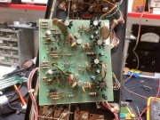
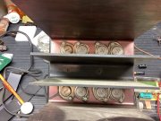
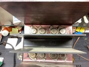
I am new to this forum. I have a new-to-me PL400, first series, 8 fin, 14B driver board, SN 8396. It has PL909 OTs in one channel and NEC 2SD555 in another. Drivers on both channels are RCA 410. I have it all cleaned up and inspected. I found the OTs all test good as do the RCA 410s. I replaced all the electrolytic caps on the 14B board and I’ve order new Kemet 9100uf 100v filter caps and some new 200mv incandescent bulbs for the meters from mouser. I can’t find any bad transistors on the board although Q4 does look to be installed wrong. I’m guessing the drawing is wrong as well. It shows them facing one another.

I’d prefer to bring this up on a Variac protected by a 120w DBT so that I can monitor the emitter currents. I read on another form that the use of a variac was problematic but that statement was made without explanation as if it was a known issue. Can someone comment on that. I’d hate to blow up the OTs. I’m not convinced a DBT offers much protection for improperly biased OTs in such large numbers.

Here is some amp porn for you.
7AD34C36-B487-493A-BBC6-993861AE5812.jpeg 14E6525A-3589-4792-ADE6-D04462388852.jpeg
 

Attachments

laatsch55

Administrator,
Staff member
Joined
Jan 14, 2011
Messages
74,272
Location
Gillette, Wyo.
Tagline
Halfbiass...Electron Herder and Backass Woof
#2
A DBT is amazingly simple and amazingly effective. A variac will not limit current, only voltage. Use both in series...serious protection then.
 

mlucitt

Veteran and General Yakker
Joined
Jun 24, 2011
Messages
3,374
Location
Jacksonville, FL
#3
Your output transistor mix is fairly standard for a forty year old amplifier. We see a lot of that. The service manual states to not mix transistor types in a column, so you are good - for now. If you want a reliable, optimum set of output transistors, invest in (12) Onsemi MJ21196G. Or better yet, upgrade the amplifier to full complementary operation with the White Oak Audio Backplane kit:
https://www.whiteoakaudio.com/estore.aspx
 

dcmeigs

New Around These Parts
Joined
Apr 6, 2024
Messages
47
#4
What is meant by ”full complimentary operation”? I’ve seen that term used in regard to the WO upgrades but I’m not familiar with its meaning.
 

Hexis22

Chief Journeyman
Joined
Dec 28, 2022
Messages
552
Location
Wisconsin
#5
See explanation below previously posted by Joe (probably should be a sticky in WOPL tips).

https://forums.phxaudiotape.com/threads/phase-linear-400-bias-advice.11277/post-347490

What is the difference between Quasi Complementary and Full Complementary?

With fully comp circuit topology, the positive half and negative half of the signal are amplified through the final current gain sections with symmetrical circuit design through the use of NPN drivers in the plus half of the signal and PNP drivers in the minus half of the signal.

The quasi comp used NPN on the plus half, like the full comp version but the minus half had the PNP driver emulated by a combination of a small PNP transistor coupled with 2 NPN pre driver and driver instead of using PNP devices. When the Phase Linear was initially introduced, this is what the designers had available to design with so they went with it.

In the last of the PL400 and PL700 production, PL did convert to fully comp on a small number before end of life of the product.

Some benefits, amp gain is more equal on the positive and negative half of the signal. In the quasi comp version, the gain of the negative side was always higher than the positive half. The global feedback compensated for this difference however and quite effectively nulled it out.

The bias settings are now extremely close for both positive and negative half. Part of this comes from the use of precision 1% resistors in the bias resistor locations, the balance comes from the symmetrical topology.

The current limit protection circuits are also now fully symmetrical leading to a more balanced onset of protection for each of the plus and minus sides.

Of course with this PL400 Backplane board, the configuration of full comp or quasi comp is easily selected by several components, jumpers and of course the choice of output drivers.

In the full comp versions, the MJ21196 (NPN) is used in the pre driver and driver positions on the plus half and the MJ21195 (PNP) is likewise used in the pre driver and driver positions on the minus half.

The use of these outstanding drivers everywhere leads to a more robust output stage as a side benefit.
 

Gepetto

Administrator
Staff member
Joined
May 15, 2011
Messages
13,560
Location
Sterling, MA
Tagline
Old 'Arn Enthusiast
#6
There is one other very big downside to quasi comp operation that plagued PL throughout their entire quasi comp life. It is a bit technical to describe. That is that the TO-3 can is the collector. On the negative half cycle, where NPN devices were used to emulate the PNP devices that they wished they had, that large can area on the base of the TO-3 forms a capacitor to chassis ground on the output of the amp. That is because the TO-3 cans are swinging with the output signal. You can see that by looking at the schematic.

In the full comp configuration, both halves of the output signal are delivered by the TO-3 emitters, not the collectors. The cans are sitting at the static B+ and B- voltages respectively and do not swing with the output signal. In this case, that capacitance between the cans and chassis ground is actually beneficial, you want capacitance from the B+ and B- rails to ground.

This capacitance makes the PNP emulator construct marginally stable (which means marginally unstable). PL had trouble with this throughout PLs existence. I am not sure if they grasped this, I believe they did but that is just a hunch on my part.

There is much more to this but I will leave it at that. I think I posted in the past, some waveforms associated with the SPICE modeling that I did on this topic.
 

dcmeigs

New Around These Parts
Joined
Apr 6, 2024
Messages
47
#9
Thanks for the explanations guys. Very interesting stuff. My background as a hobbyist is mostly with vacuum tube circuits and it just in the last year or so that I’ve become interested in “sand”. It was by necessity as my vintage pioneer SX-880 developed a bad hum. That learning curve was so steep and so interesting I’ve become addicted. The first stereo system I heard as a teen that really blew my mind was huge JBLs driven by a PL400. I just bought a PANASONIC VP-8174A FA/AM Signal Generator to align my big Kenwood so I guess I’m hooked.
 

mlucitt

Veteran and General Yakker
Joined
Jun 24, 2011
Messages
3,374
Location
Jacksonville, FL
#11
Many of us started out with tubes. Mine was a McIntosh 225. Eventually, tubes became expensive and then very hard to find. It has become better lately, but for me the damage was done. I migrated to a Marantz 2285 and never looked back.
Now, no more foreign amplifiers for me - I just stick to Phase Linear, Carver, Krell, Mark Levinson, Audio Research, PS Audio, you get the idea.
 

dcmeigs

New Around These Parts
Joined
Apr 6, 2024
Messages
47
#12
I got my mouser order in today, replaced some transistors and a few remaining caps and she’s passing a signal again. The dc bias is set at 350mv, and the dc offset is less than 5mv on both channels. I listened to it for a while then buttoned it all up.

It was later I noticed that if I started the amp with a speaker load, the 120W dim bulb lights fully, I get a small hum from one channel and of course no signal. If, on the other hand, I power it up with out load THEN connect the speakers all is well.

I‘m beyond puzzled by this. Any ideas what I should look for?
 

dcmeigs

New Around These Parts
Joined
Apr 6, 2024
Messages
47
#19
And does a latch up typically blow fuses? I’m pretty certain this would have blown fuses had I not had it on the bench with the dim bulb.
 
Top