- Joined
- Jan 14, 2011
- Messages
- 75,755
- Location
- Gillette, Wyo.
- Tagline
- Halfbiass...Electron Herder and Backass Woof
Big caps for emphasis, wasn't really screaming , not a screamer...


When speaking of E-B-C, or such, it's a;lways referred to with a certain orientation. Around here, it is with the flat facing you and the legs down. the TO-39's have the same pinouts, don't sweat those. The TIS-97's, and TIS-93's you have are Fairchild Semiconductor devices and the pinots are direct from their website...
TIS-97 with orientation stated above---Collector --Base--Emitter
TIS-93"""" """"""""""""""""""""""""'---Same
MPSA 93--'''-----------'''----------------Emitter ---Base---Collector
Thanks for the heads up with the cap leads, I'll bend accordingly.
One of your e-mails read "Q3,Q4 get the small, flat heatsink" so I assumed (god I do that a lot) that 4 were needed.
You sent three brown poly film caps. Where do those go?
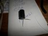
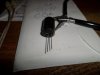
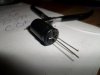
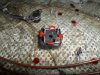
Following are pics of Q1-Q4 that I installed using the Layout Diagram to identify. Q1 & Q2 are TIS-97 - Q3 are TIS-93 and Q4 are MPSA93
View attachment 14269View attachment 14270
What's up with all the other flying connections that I see going on?
The .o1uf/400 volt go on the 4 legs of the bridge rectifier as switching noise snubbers. Should have been 4 of them...
Here ya go...