How are the measurements on the left channel? and just for shits and giggles, lift one leg of D13 and check it. They test .79-.80 in circuit both ways....
Did not check D13's in circuit, should I have done that? I jumped right to lifting a leg and they were both .55 volts one direction - OL in the other.
Found the same anomaly at Q3 - voltage in one direction between emitter and collector.
Noticed that the trace hole for Q4 collector has lifted but it's still attached and I'll deal with it later.
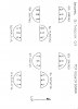
Left channel transistor readings:
Q1
OL - red to base & black to emitter
OL - red to base & black to collector
.67 volts - red to emitter & black to base
,67 volts - red to collector & black to base
OL - red to collector & black to emitter
OL - red to emitter & black to collector
Q2
OL - red to base & black to emitter
OL - red to base & black to collector
.67 volts - red to emitter & black to base
,67 volts - red to collector & black to base
OL - red to collector & black to emitter
OL - red to emitter & black to collector
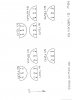
Q3
.65 volts - red to base & black to emitter
.65 volts - red to base & black to collector
OL- red to emitter & black to base
OL - red to collector & black to base
.86 volts - red to collector & black to emitter
OL - red to emitter & black to collector
Q4
.61 volts - red to base & black to emitter
.58 volts - red to base & black to collector
OL- red to emitter & black to base
OL - red to collector & black to base
OL - red to collector & black to emitter
OL - red to emitter & black to collector