You can't run with 580mV on the right channel unless you want a meltdown.

You are using an out of date browser. It may not display this or other websites correctly.
You should upgrade or use an alternative browser.
You should upgrade or use an alternative browser.
700/1 “Tim” WOPL driver board
- Thread starter AngrySailor
- Start date
AngrySailor
Veteran and General Yakker
- Joined
- Oct 15, 2014
- Messages
- 3,419
- Tagline
- ---not quite right
RCA 410’s if I remember right...
AngrySailor
Veteran and General Yakker
- Joined
- Oct 15, 2014
- Messages
- 3,419
- Tagline
- ---not quite right
They are RCA 410’s
MarkWComer
Veteran and General Yakker
- Joined
- Nov 1, 2014
- Messages
- 3,520
- Location
- Gaston, SC
- Tagline
- Victim of the record bug since age five
Looks like I jumped into this without knowing a thing about your amp.There are also two testpoints on the backplanes for bias+ and bias - in addition to the one on the driver board, which is positive. If you use the TPs on the backplanes, you should get the same values but opposite polarity.
It’s measured against the speaker/meter outputs OR the “output” TP on the backplane.
Given that there are bias +/- on the backplanes, does this mean that the NPN/PNP banks could “mis- bias” due to an emitter resistor or transistor fault independently and cause a thermal runaway in one column only?
I can be an ass sometimes…
MarkWComer
Veteran and General Yakker
- Joined
- Nov 1, 2014
- Messages
- 3,520
- Location
- Gaston, SC
- Tagline
- Victim of the record bug since age five
With that in mind I’m pleased to say that my 700/II is very symmetrical!It means that I put them on there so the inquisitive folks on this forum could check the top to bottom symmetry on their full comp amps")
Thanks- I didn’t understand your purpose in this.
Knowledge increased, education continues…
Yes it is a bell and whistle Mark, but when you are investing in an upgrade, it is nice to have a test point instead of having to clip your test leads across a resistor somewhere on a PCB assembly.With that in mind I’m pleased to say that my 700/II is very symmetrical!
Thanks- I didn’t understand your purpose in this.
Knowledge increased, education continues…
AngrySailor
Veteran and General Yakker
- Joined
- Oct 15, 2014
- Messages
- 3,419
- Tagline
- ---not quite right
HAHA Mark! No worries. Guess I’ll pull all the outputs on the right channel and go from there.Looks like I jumped into this without knowing a thing about your amp.
I can be an ass sometimes…
And also recommend you get rid of those 555s while you are in there.HAHA Mark! No worries. Guess I’ll pull all the outputs on the right channel and go from there.
AngrySailor
Veteran and General Yakker
- Joined
- Oct 15, 2014
- Messages
- 3,419
- Tagline
- ---not quite right
Yeah they were from Linda and new or something??! I can’t remember but I had a full set of them. I might have enough MJ’s for one channel if I rob them from Linda’s build for now.And also recommend you get rid of those 555s while you are in there.
Yeah they were from Linda and new or something??! I can’t remember but I had a full set of them. I might have enough MJ’s for one channel if I rob them from Linda’s build for now.
There is a good reason there are no Japanese transistor companies anymore
AngrySailor
Veteran and General Yakker
- Joined
- Oct 15, 2014
- Messages
- 3,419
- Tagline
- ---not quite right
There is a good reason there are no Japanese transistor companies anymore

62vauxhall
Veteran and General Yakker
- Joined
- May 14, 2014
- Messages
- 2,367
- Location
- Southwest Kootenays BC
- Tagline
- No such things as bad days, just bad moments
I am old enough to have had my childhood in the 1950's. The general attitude among my parents and their social circle was that"Made in Japan" meant utter cheap junk. I had battery powered robots and cars given to me and can attest that they broke or stopped working soon after I began playing with them. But they were cheap to buy. If that were not so, I wouldn't have gotten them.
In the 60's "Made in Japan" began having less of a stigma. My belief is the proliferation of solid state devices and manufacturing in general along with R&D began to set "Made in Japan" as a hallmark of quality. And that was carried through into the 1970's which might have been the apex of Made in Japan" quality assurance.
And then "Made in Korea" had the distinction of being the cheapest and lowest of the low in terms of quality acceptance. Then their game was upped and "Made in Korea" began to be considered a viable alternate to "Made in Japan".
It was about then I began empoloyment in consumer electronics. "Made in Malaysia" made it's appearance as did "Made in Hong Kong", "Made in Singapore" and other "Made in's" that don't come to mind at the moment.
And now it is "Made in China" that's been getting the bad rap. But that population and manufacturing base is huge as is the global market so as far as I'm concerned, manufacturing quality ranges from extreme to extreme. My thought is that good stuff can come from there but foreign importers like North America, chose to buy what's most cheaply available and take their chances with failure rates.
I suspect that Japan's semi-conductor industry still produces viable products but the primo stuff is not exported due to price competion with the likes of China. Maybe only factory seconds or stuff not subject to quality control are sold abroad?
MarkWComer
Veteran and General Yakker
- Joined
- Nov 1, 2014
- Messages
- 3,520
- Location
- Gaston, SC
- Tagline
- Victim of the record bug since age five
I took them apart when they stopped working, the stamped metal had a different toy printed on the inside. Perhaps the metal was recycled and they sent us the cheap junk?I had battery powered robots and cars given to me and can attest that they broke or stopped working soon after I began playing with them.
Wheel-right
Chief Journeyman
American beer can material from the soldiers stationed there? I got no complaints about my Japanese stereo equipment, it just keeps on playing. 60's and 70's stuff.
AngrySailor
Veteran and General Yakker
- Joined
- Oct 15, 2014
- Messages
- 3,419
- Tagline
- ---not quite right
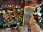
All outputs removed from right channel. Bias now 13v
Your 10 ohm bias resistor would be smoked with 13v across it
16.9W!!!
16.9W!!!
AngrySailor
Veteran and General Yakker
- Joined
- Oct 15, 2014
- Messages
- 3,419
- Tagline
- ---not quite right
The smoke would have been out of that poor 10 ohm 1/2W resistor long ago with 11V across it. I would doubt that resistor measures 10 ohms. Is it cracked? (Not in the Hunter sense)
There is indeed too much voltage across that resistor. Seems like an intermittent short to ground on one or more of the tranny sockets. It will measure anywhere from 11v down to ~70mV with some wiggling around.
Hi Andrew
I think I see the leads of the RCA410s poking through the sockets at the bottom. Can you confirm? If yes, good.
The body of the 10 ohm resistor you are measuring is far offset to the right and very close to the blob that is the connection of all the upper bank emitter resistors.
Are you sure there is really a connection to the blob for that resistor? Or is the right end connection intermittent to the blob?
Blob is one of my favorite words, use it nearly daily...
mlucitt
Veteran and General Yakker
I had a 10 Ohm resistor that was cracked right on a black color band, very hard to see, you may want to move it slightly.
Also, it is a routine maintenance technique on those original transistor sockets, when the transistors are removed, to pinch the connection points for the Emitter and Base pins with a small pair of wire cutters to push them back together.
Also, it is a routine maintenance technique on those original transistor sockets, when the transistors are removed, to pinch the connection points for the Emitter and Base pins with a small pair of wire cutters to push them back together.