You are using an out of date browser. It may not display this or other websites correctly.
You should upgrade or use an alternative browser.
You should upgrade or use an alternative browser.
400 Series 1 Build
- Thread starter Hexis22
- Start date
Control board mounted, wired up, and +/-15V supply voltages confirmed.
All output drivers installed and each TO-3 case confirmed isolated from chassis ground.
Initial Bias set to 350mV after 5 min power up.
Output offset on both channels measured 0.1mV.


All output drivers installed and each TO-3 case confirmed isolated from chassis ground.
Initial Bias set to 350mV after 5 min power up.
Output offset on both channels measured 0.1mV.


Pulpmillguy
Journeyman
The speaker output DC protection PCB is from Don, with my components and assembly.Nice clean build. Great work and always something to model your own after.
Whose output relay board is that? Is it Joe's or Don's?
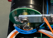
Also, what is that circuit board that is on top of the power supply filter caps?
View attachment 78701
Never seen anything like that before. Does it come with them or is it an adder?
The power supply cap assemblies are from White Oak. The PCB converts the caps solder terminals to screw terminals.
MarkWComer
Veteran and General Yakker
- Joined
- Nov 1, 2014
- Messages
- 3,520
- Location
- Gaston, SC
- Tagline
- Victim of the record bug since age five
Very clean looking job- beautiful work!
Thank you!Very clean looking job- beautiful work!
I try to build every project as if it were my own equipment. The internal construction means more to me than outward appearance, not to say I don't like a sexy outer appearance...
Every solder joint, wire placement, and component is finished with purpose.
That is the way they were supposed to be originally built Eric. Very nice.Fully assembled, tested, and ready for playing music and burn in.
After building several 700's, this 400 is a dream to work on with respect to weight and complexity.


wattsabundant
Chief Journeyman
I noticed on the relay board that R6 and C3 are not populated. This snubber protects the chip from the inductive kick of the relay coil. The values are .1uf and 100 ohm. The alternative is a clamp diode (1N4004) across the coil on the back side of the board with the cathode on pin 8. The snubber or diode is necessary for proper operation.
These days I use the diode and install an LED and current limiting resistor in place of the snubber. The LED lights when the relay pulls in. The clad will eventually get changed when I run out of the existing stock.
These days I use the diode and install an LED and current limiting resistor in place of the snubber. The LED lights when the relay pulls in. The clad will eventually get changed when I run out of the existing stock.
Don, thanks for the comment.I noticed on the relay board that R6 and C3 are not populated. This snubber protects the chip from the inductive kick of the relay coil. The values are .1uf and 100 ohm. The alternative is a clamp diode (1N4004) across the coil on the back side of the board with the cathode on pin 8. The snubber or diode is necessary for proper operation.
These days I use the diode and install an LED and current limiting resistor in place of the snubber. The LED lights when the relay pulls in. The clad will eventually get changed when I run out of the existing stock.
I placed a 1N4004 diode on the underside of the board across the coil.
I just omitted the LED and current limiting resistor you place on R6 and C3.
Thanks Joe.That is the way they were supposed to be originally built Eric. Very nice.
Your designs and kits are first rate and make assembly enjoyable.
gene french
Veteran and General Yakker
- Joined
- Mar 6, 2022
- Messages
- 5,887
- Tagline
- music...the healer of souls...
wish i had some of your talent and patience...LED meter lights installed and wired up.
Meter level sensitivity leads connected to switch.
Assembly sticker added to upper cap.
Final assembly and testing next.


- Joined
- Jan 14, 2011
- Messages
- 75,859
- Location
- Gillette, Wyo.
- Tagline
- Halfbiass...Electron Herder and Backass Woof
wish i had some of your talent and patience...
You do, you just fail to manifest it....
gene french
Veteran and General Yakker
- Joined
- Mar 6, 2022
- Messages
- 5,887
- Tagline
- music...the healer of souls...
i appreciate your confidence in me...i really do...You do, you just fail to manifest it....
that work is impeccable ..
gene french
Veteran and General Yakker
- Joined
- Mar 6, 2022
- Messages
- 5,887
- Tagline
- music...the healer of souls...
i got that tee short too!!!
lololol


