PL400 II Resurrection
- Thread starter TapeHeadOne
- Start date
Checking a very old cross reference catalogue of undetermined origin, it states as substitutes for the RCA 410 :
MF410
SDT410
BUS21
D44TE3
IR410
PTC410
I think I'm going to look closer at that BUV21...I may have something there. Anyone wants to pitch in, feel free.
Meanwhile I've started the WO board repair, and I think I may get away with it.
MF410
SDT410
BUS21
D44TE3
IR410
PTC410
I think I'm going to look closer at that BUV21...I may have something there. Anyone wants to pitch in, feel free.
Meanwhile I've started the WO board repair, and I think I may get away with it.
RCA410
66546
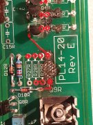
Are your current drivers shot or not? You only need 2, second and 4th column from the transformer.
I'll give it a go, Gepetto.
I'm not stopping the hunt though,. Now in order to find a suitable replacement, and providing the voltage levels are acceptable, it occurs to me that the principal factors for a suitable replacement would be :
- the gain
- the transition frequency
- the Max e-b voltage
Voltage and Wattage don't seem to be a problem.
We would like the gain to be close, for obvious reasons
The transition frequency can be a problem, as it's essentially a low pass filter and feeding all kinds of funky frequencies to the output stages that don't belong can affect things adversely. The RCA410 is a 2 MHz part, but since the new 21196's transition at +4 MHZ I figure 2.5, 3 or even 4 isn't going to affect things.
The one I've omitted so far is speed. This can be an issue when the driver switches substantially faster than the stages. But since we're dealing with modern parts on both ends, and I don't really know what the data are, I'm going to studiously ignore it.
This said, I looked up the RCA 410 on alltransistors and hit the cross reference button. It spewed out a colossal list most of which seem equally obsolete as the original.
I then copied the whole caboodle to excel and hit the filter data button. It now allows me to filter per spec.
What's immediately obvious is that the issue is the gain of 10. The only 'existing' replacement with the same specs is the MH423. It's still on the Mouser books as an existing part, but not stocked. I have no further data on it.
Carefully jacking the gain up to 15 yields the first - very small - batch of possible suspects, principal of which are the MJ15022 and 15024.
So while at this time I'm going to try what Gepetto says, running with 1 driver per channel, If it works I'm going to try with those replacements to see what happens. Who knows, maybe I'll blow it up again !
Edit : the 80V on the left channel is coming from elsewhere. I figure it must be coming from the pre board. Which means it would have to disappear when I desolder the unfused 80V from that board.
Edit 2 : I can find no errors in the wiring on the old input board. Disconnecting the 80V unfused from the input board drops the outputs to around zero.
Well, it wouldn't, wouldn't it. Which is weird, because the burn-outs were in the right channel, all the transistors in the left escaped unscathed.
Pete
Last edited:
Phase Linear Pre-Driver and Driver Selection
This post is to provide a set of guidelines for selection as the sources for original devices are drying up and substitutes will have to be sought.
First let's get the definitions clear:
Pre-Drivers are classic RCA410 location. Typically Q11 and Q12 in the PL400 and the PL700B.
Drivers are the classic PL909 location. Typically Q13-Q18 in the PL400 or Q13-Q22 in the PL700B.
Pre-Driver Requirements (less demanding than the Driver requirements):
TO-3 Package
Vce = 200V min.
Slow, Ft less than 1/2 of the output device. Or alternatively 2X it. But not the same. The larger separation, the better. This requirement affects the negative half side of each channel (typically Q12) in order to ensure stability of the quasi-PNP transistor that is formed by the local feedback combination of Q7, Q12 and Q14, 16, 18 (also Q20 and 22 for the PL700B). The positive half side of each channel can use the same Pre-Driver as the Driver as there is no such local feedback condition on the positive half.
Low current gain (this contributes to the low Ft).
Lower noise is better (hardly ever specified, determined by measurement)
Recommended devices (in order of preference, the first 2 were the only types specified by Phase Linear): RCA410, SJ2741, MJ410, MJ413, MJ423. possibly 2N6678
Driver Requirements:
TO-3 package
Vce>= 250V
Large SOA, especially ability to sustain more current in the 50msec range at 200V (160V for the PL400) is important. The more current it can withstand, the better. The 21196 is well suited in this regard in that it will safely sustain 1.5A for 50msec at 200V (this is the half sine-wave time duration for a 10Hz signal).
Ft >= 2X the predriver is ideal, the higher the better. Minimum 4MHz is acceptable, higher is better.
Lower noise is better (hardly ever specified, determined by measurement)
The more current gain, the better. The 21196 has hFE between 50-75 at 3A.
Recommended devices (in order of preference): MJ21196, MJ21194, MJ15024
What is the difference between Quasi Complementary and Full Complementary?
With fully comp circuit topology, the positive half and negative half of the signal are amplified through the final current gain sections with symmetrical circuit design through the use of NPN drivers in the plus half of the signal and PNP drivers in the minus half of the signal.
The quasi comp used NPN on the plus half, like the full comp version but the minus half had the PNP driver emulated by a combination of a small PNP transistor coupled with 2 NPN pre driver and driver instead of using PNP devices. When the Phase Linear was initially introduced, this is what the designers had available to design with so they went with it.
In the last of the PL400 and PL700 production, PL did convert to fully comp on a small number before end of life of the product.
Some benefits, amp gain is more equal on the positive and negative half of the signal. In the quasi comp version, the gain of the negative side was always higher than the positive half. The global feedback compensated for this difference however and quite effectively nulled it out.
The bias settings are now extremely close for both positive and negative half. Part of this comes from the use of precision 1% resistors in the bias resistor locations, the balance comes from the symmetrical topology.
The current limit protection circuits are also now fully symmetrical leading to a more balanced onset of protection for each of the plus and minus sides.
Of course with this PL400 Backplane board, the configuration of full comp or quasi comp is easily selected by several components, jumpers and of course the choice of output drivers.
In the full comp versions, the MJ21196 (NPN) is used in the pre driver and driver positions on the plus half and the MJ21195 (PNP) is likewise used in the pre driver and driver positions on the minus half.
The use of these outstanding drivers everywhere leads to a more robust output stage as a side benefit.
I've made list containing what's necessary to do a refurb of my existing input board. I had to get creative with some of the transistors, obviously, and the 1N4848's. I hope I got all the right parts. This is for my PL36. I don't know what your board looks like.
I think it's going to set you back around 50-60 bucks, because them LF356's are expensive.
Comments welcome.
Cheerio, Peter
I think it's going to set you back around 50-60 bucks, because them LF356's are expensive.
Comments welcome.
Cheerio, Peter
Attachments
-
18.3 KB Views: 12
Last edited:
I've made list containing what's necessary to do a refurb of my existing input board. I had to get creative with some of the transistors, obviously, and the 1N4848's. I hope I got all the right parts. This is for my PL36. I don't know what your board looks like.
I think it's going to set you back around 50-60 bucks, because them LF356's are expensive.
Comments welcome.
Cheerio, Peter
I think it's going to set you back around 50-60 bucks, because them LF356's are expensive.
Comments welcome.
Cheerio, Peter
First you want to upgrade to lf351 op-amps. The R1,R2 increase value to 7.5 k 5 watt. This produceds a lot less heat.
I think if you spent a little time looking at some past threads it will help you get the newest parts to use.
All new resistors should now be metal film aside R1 R2 with can be wire wound.
My objective was to install the WO board as an upgrade and then to 'restore' the PL36 to 'original'. This is why I went for the 356 and 1.8K. That aside, there is simply too much information available on the 'net'. I'll get there when I get there.
All mentioned resistor part numbers are 1% Xicons (same as the WO boards) and the R1/R2's are wirewound. I've also tried and get film caps where practical.
On my last order to try and fix the WO board I forgot to order the 133 Ohm resistors, and they're coming in now. So first order of business will be to see if that will work. If it's beyond salvation, I don't know what I'm going to do yet.
I've also started a 'project' of making a full mono (1 box per channel) 'new' PL400II.
Last edited: