BIG problems

Did you solder the leads on the 2N3415 in the correct order? They are not the same as most TO-92 transistors are.

When looking at the transistor flat with leads pointing down on both transistors is E-C-B. E= Black Wire, B= Brown Wire, C= Red Wire

If they are mis-wired, you will not get the desired bias effect.

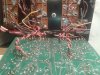
Something doesn't jive. The wires on the board end are as follows:

Red= Collector
Black= Base
Brown=Emitter

Please confirm
 
That's what they are on most amps I've done. Timee to confirm that Mike. Do the BE,BC junction test. GENERALLY----meaning NOT always, the BE junction will read a little more than the BC junction.
 
That's what they are on most amps I've done. Timee to confirm that Mike. Do the BE,BC junction test. GENERALLY----meaning NOT always, the BE junction will read a little more than the BC junction.


What I did was trace the wire/board termination and came up with the above.
Joe`s transistor pinout confirms the one I had on hand but his wire color to pin reverses E and B :confused2:
 
Last edited:
Entirely possible, depends on who and what day the amp was wired, not to mention if it was after the afternoon...........um...break.
 
Left channel as it was, Right channel changed. I started to measure upwards of 8volts real quick in that configuration (Right Channel) while bringing up the variac before I shut `er down.
 

Attachments

  • 2013-10-04 00.35.18.jpg
    2013-10-04 00.35.18.jpg
    96.3 KB · Views: 28
8 volts isn't enough to have the front end in control, start habving 3 headed green babies when it gets to 60 volts and it's still doing it.
 
If you have the 18's and 92's in Q1-Q4 , probably not. I have been in pure bias hell without hurting those parts.
 
Reverse the C and E leads on the right channel where they go on the board.
 
Mike, black on the right side is the emitter, the center pin is the collector, the right pin is the base.
 
I'm confusing you AND me. On the right side the board connections from left to right are, collector, base, emitter. in the tranny ,as Joe said as the flat is toward you and the leads facing down, from left to right, emoitter collector, base.
 
Reverse the black and brown wires where they enter the board on the right side.
 
The transistors are wired different on the pin ends, look at em, not the same colors for the same pins...
 
I'm confusing you AND me. On the right side the board connections from left to right are, collector, base, emitter. in the tranny ,as Joe said as the flat is toward you and the leads facing down, from left to right, emoitter collector, base.

Correct. See picture of Left channel
 

Attachments

  • 2013-10-04 00.35.18.jpg
    2013-10-04 00.35.18.jpg
    96.3 KB · Views: 36
OK, there are some wires in the way of seeing the pin terminations at the bias tranny on the left. It appears the red is the collector on both. (center pin) . Don't be confused by the holddown bolt being on the right instead of the left. That tranny can go in that P-strap either way. Both bias tranny's , the flat is facing AWAY from you, try that.
 
Back
Top