- Joined
- Jan 14, 2011
- Messages
- 75,918
- Location
- Gillette, Wyo.
- Tagline
- Halfbiass...Electron Herder and Backass Woof
Thank you Joe, I will do just that....

Thank you Joe, I will do just that....
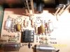
C108,C208,C115, C215, C119 C219, C116, C216, C5, C209, C210, C109, C110,C114, C214, ????????All ceramics Joe.
C103, C104 are polystyrene... they stay. C101 was a tantalum, it's gone, C102 is a ceramic. R101-104 are MF or MO.
C101, 201 must be low leakage types Lee. That is why they used a tantalum. You would be much better served however to put a low voltage Polypropylene or Polyester in that location if you can fit it.
That is a critical cap and should not be replaced with an aluminum.
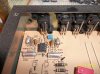
Really funny Lee after seeing that photo. All that bare board space and PL did not leave room for good components.Not much room to parallel 3, but I'll figure something out.....
Yes Joe, have taken your subs to heart and hace a mouser order going out tonight. So even the ones that look like MF are CF, or CC??
")