- Joined
- Jan 14, 2011
- Messages
- 75,812
- Location
- Gillette, Wyo.
- Tagline
- Halfbiass...Electron Herder and Backass Woof

If I am understanding your post correctly Lee, when left channel bias is set to minimum, you achieve an offset of 0.004V but when you turn the bias up to maximum, you get an output offset ranging from +16 to +25VDC and then it slowly drifts down.
Did I get that correctly?
Frustrating to write a long response and then have the website dump you when you hit submit response.
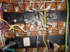
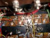
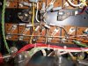
The second observation is what is that small orange or tan resistor looking item halfway up that same stack going from the output driver base bus wire to the junction of all the 0.27 ohm emitter resistors? Is that a replacement R39?
OK that is twice I have gotten dumped by Phoenix this morning. Is something in process, like a backup?