
- Joined
- Jan 14, 2011
- Messages
- 75,529
- Location
- Gillette, Wyo.
- Tagline
- Halfbiass...Electron Herder and Backass Woof
Good man, glad to seee you doing your part!!
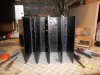
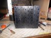
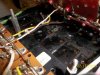
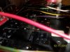
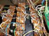
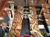
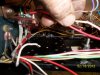
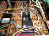
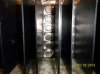
I use crude oil condensate to clean the heatsinks, took all of 3 minutes. Don't know what's in the stuff but as soon as it makes contact the dreaded white grease is on the run. To give you an idea of it's vbapor presure, when it's 80 degrees outside, you can watch it evaporate/.
I use crude oil condensate to clean the heatsinks, took all of 3 minutes. Don't know what's in the stuff but as soon as it makes contact the dreaded white grease is on the run. To give you an idea of it's vbapor presure, when it's 80 degrees outside, you can watch it evaporate/.

")