White Oak- Phase Linear Driver Board Tester

laatsch55

Administrator,
Staff member
Joined
Jan 14, 2011
Messages
75,551
Location
Gillette, Wyo.
Tagline
Halfbiass...Electron Herder and Backass Woof
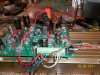
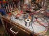
I think we are getting there. Joe---a couple questions; does the power supply need filtered with 22,000 uf or will say 1900 X 2 do it?? I realize there is little current involved hence the AWG 24, TR-64 105 deg wire. What exactly are the criteria for getting good, filtered DC??
 

Attachments

  • 100_1618.jpg
    100_1618.jpg
    88.1 KB · Views: 60
  • 100_1617.jpg
    100_1617.jpg
    100.3 KB · Views: 58
  • 100_1616.jpg
    100_1616.jpg
    96.3 KB · Views: 57
  • 100_1615.jpg
    100_1615.jpg
    98.2 KB · Views: 59
Last edited:
Hi Lee
In order to keep my test rig portable, I use my HP lab power supplies (regulated and current limited) as the power source. Each B+ and B- rail is bypassed with a 1000uF 100V electrolytic where the power source enters the test board. This is not a high power test you are conducting so that should be more than adequate.
 
YO!!! Dr. Lucitt!!! Bought to power this puppy up. Had to pop in some 5088's for bias, almost forgot that. Soon as the 5 minute is cured in they go. If I take AC from the wall run it through a BR and some caps that gives me 82 +,82- DC. Is that going to F^%$ with my scope not having a transformer in line to isolate the earth ground??
 
Figured that, had to ask though. So it's the ground that does the damage because, with a two wire you can never be sure which is neutral and thus eventually ground??

Progresas....After some thought, it seemed mini grabbers were the answer for the bias hookup. The 10 pin connector is used AFTER layering solder on the pins and a little filing to make sure of contact.
 

Attachments

  • 100_1623.jpg
    100_1623.jpg
    95.9 KB · Views: 75
  • 100_1622.jpg
    100_1622.jpg
    91.5 KB · Views: 44
  • 100_1621.jpg
    100_1621.jpg
    98.8 KB · Views: 44
  • 100_1620.jpg
    100_1620.jpg
    96.4 KB · Views: 45
Good thing you didn't plug that puppy in with your scope grounded. It would have been pretty for about one cycle or 16.6 milliseconds, give or take.
 
The Leader has an onboard battery for those iffy situations. Use it that way in the field that way.
 
In the Navy we used a cheater plug on our o'scopes to lift the ground and bring the test equipment to the floating level of the unit under test, but you had to be careful 'cause the whole o'scope chassis was "live" and if you forgot your gloves and touched the scope while you were hanging on to the cabinet, you got bit. Sometimes it was the only way to see the logic gates; everything on a ship is grounded to the hull and it is one noisy chunk of steel.
 
How did your field call work out?

BTW, we just started getting light rain. We are 50 miles West of Washington, DC. The federal government is shut down tomorrow, so I will be at home.
 
Yeah we have used the ground floater cheater technique but it is very unsafe. You have to keep your wits about you when using that mode.
 
The field call worked out to a " We'll finish Monday". OK, found a tranny that gives me +81, -81 VDC. I have scrapped A LOT of electrical and electronic equipment over the years and HAVE NEVER thrown out a transformer. I have BOXES of transformers. Sometimes it takes awhile to find the right one, but I usually do. Scope and AP are warming up.
 

Attachments

  • 100_1624.jpg
    100_1624.jpg
    97.8 KB · Views: 43
Yeah we have used the ground floater cheater technique but it is very unsafe. You have to keep your wits about you when using that mode.

well, we now how that usually works around here.............................
 
Building one of those now Dennis...
 
Last edited by a moderator:
Lee, That looks like a nice old shielded audio transformer from a 1933 Philco radio. You are a funny guy.

Mark
 
Has the nice copper belly band like the Crown DC300 has on it Mark. No stray flux in Lee's test setup :-)
 
That transformer came from a mixing board I tore down 2 weeks ago. It wasn't the Peavey, it was the other one. It was made in 1972. It was the "Carvin" board.
 
Last edited:
Lee,

Here's an idea for a test fixture. I've used something very similiar to this to test populated circuit boards. Good luck with the testing.

http://store.merifix.com/


Dennis I'm still trying to understand that, but is it saying you can custom cut a probe board to lower the driver(or any) board down on it and have all the test points accessible??
 
The temporary nature of the connections is causing some slight irritations and buckets of frustrations. Sir Joe, what do you make your temporary connections with?? Should the bias be the same??
 
Back
Top