Dnspy007
Journeyman
Thank You, SirYes, +/- 84V rail voltage with 120V AC input looks correct.
Party on…
ROCKIN' ON.......................Slooooooooly
Thank You, SirYes, +/- 84V rail voltage with 120V AC input looks correct.
Party on…
Nice work. Yer gonna love the 400 II WOPL. I listen to mine daily and I have my 700 II WOPL sitting in the rack since I finished it about Jan, I put an hour on it and I haven't fired it up since.
I am going to wire up the 700 II WOPL and use it for the bottom end and use the 400 II WOPL for the high end. Been to busy to get that done but it's going to be miserable hot and humid today (heat index of 100) so maybe I'll get motivated and do it when I finish testing this Carver C-4000 this morning. No yard work till tomorrow (a high of 72, go figure). I think I may build another 400 II WOPL IF...... I can find another 400 II Faceplate like the one I got from Glen with holes in it for a power switch and display switch. Or, I can cheat and just slap a 700 II faceplate from Joe and say to hell with it. Get your's going, yer almost there.
Thank You, For kind words Sir.
With all the good reviews on these Amps after the WOPL builds, I'm pretty sure I'll Love....Right now, Just hoping this things gonna work when I get it done. If everything goes well this build, I have a couple of 700 ll's, Planning to do the Full WOPL treatment.
This heat can make a man want to stay inside. Thank you for that idea.. "No Yard Today". I believe I'll continue on with my build....


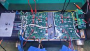
Now doesn't that look much more professional inside than it did originally? Wait till you hear the sound it produces...Control Board installed....No Shorts, No blown fuses, No Smoke, No shorts to Transistor Cans, Voltage present at B+/B- rails also, All pad voltage close to safe mode bring up chart, 0 volts at R/L outputs. Noticed a drop in voltage. I take that as being normal, Due to installation of the Control Board and its components. Not really sure, This being my first attempt at this type of build.
Thanks for looking............
View attachment 86929
View attachment 86930
Now doesn't that look much more professional inside than it did originally? Wait till you hear the sound it produces...
When you add the control board, you get the bias loading which moves the rail voltages down slightly.
Joe is generous with the wire lengths going from the Backplane Boards to the Control Board to make sure you have enough. You can certainly trim them so that the bottom cover does not come into contact with them. Completely optional. Measure twice, cut once!Control Board installed
Joe is generous with the wire lengths going from the Backplane Boards to the Control Board to make sure you have enough. You can certainly trim them so that the bottom cover does not come into contact with them. Completely optional. Measure twice, cut once!
Input Jacks look great!
I install the thin Nylon washers under the Control Board and under the two Retaining Nuts because I have to remove/replace the Control Board often during a rebuild. And it helps on my Bench Test Mule Amplifiers that I use to test Control Boards for customers. I should install wingnuts!Just in case I had to remove Control Board..
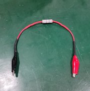
Yes, the caps will discharge. As Mark mentioned that he does, I also use a 200 Ohm 5W bleeder resistor and (2) small alligator clamps wired into each end, and after installing a row of T/O's I discharge the caps quickly. I made two of those small bleeders, and I use them on everything, A/C repairs, welding machine repairs etc. They are handy, and sure beat shorting a screwdriver across the cap !!!! (I've seen guys do it !!!)Got a question before I install 2nd row of Transistors. Is it normal for the caps to discharge at this stage of the build?
Reading a few minutes after powering down....
View attachment 86934

Yes Sir,Yes, the caps will discharge. As Mark mentioned that he does, I also use a 200 Ohm 5W bleeder resistor and (2) small alligator clamps wired into each end, and after installing a row of T/O's I discharge the caps quickly. I made two of those small bleeders, and I use them on everything, A/C repairs, welding machine repairs etc. They are handy, and sure beat shorting a screwdriver across the cap !!!! (I've seen guys do it !!!)
I believe you will find this noted in Step 13 of the "Bring Up Instructions, although it may be in a different location for the 400 bring up:
" 13. Remove AC power and use a ~200 ohm, 5W resistor to discharge the 2 bulk caps down below ½ volt."
View attachment 86935


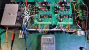
You're getting close...........you will be making incredible music soon !Finished install and Testing of the 2nd row of Transistors. No Shorts, Blown fuses, Smoke, Shorts to Transistor Cans, Voltage present at B+/B- rails, 0 volts at R/L outputs, All pad voltage close to safe mode bring up chart, Checked Bias, hanging around 0.348v still in the perimeter.
Thanks for looking.....
View attachment 86937
Rockin' on to Row 3
The Bias reading will probably not change much, now that you have two rows of Output Transistors installed. The real Bias check is after all your Output Transistors have been installed and the amplifier has been producing some serious music for thirty minutes or so - it will be nice and warm.Checked Bias, hanging around 0.348v still in the perimeter.
