AIWA AD-F880-MAX , my own heavily modified version of this deck.

vince666

Chief Journeyman
Joined
May 15, 2013
Messages
1,053
Location
deep south of Italy
Tagline
I will not be missed! :p
#1
Hi guys,

finally my own project on one of my AIWA AD-F880 , started a long time ago and where I've applied a long series of modifications, is quite ready!

These first few post are just a teaser... as soon as I gather all the details, schematics, ect, I will add them here in this thread.

At first, the deck had all the mods by Alex/ANT applied, to make it an AIWA AD-F880M (new op-amps on PB and REC amps, a few capacitors, a couple resistors, a couple diodes).

Also, this deck had quite a bit worn heads, which I've lapped and got improved but I wasn't too satisfied and was hoping to replace them with some new heads.
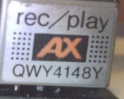
So, a while ago, I've found some nice "AX" amorphous heads (an original spare for some 80's TOTL Technics models) which were missing the fork guide and the guide was intended to stay at left/REC side... So, I've managed to take the guide from a broken head and put it on the right/PB side, as needed to fit and work in the AIWA deck. (not an easy work! I had to design and DIY a tool to properly align the guide and also modify the mounting plate as the screw holes resulted to be skewed horizontally and the head couldn't stay at the proper place).
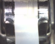
01_AX heads.jpg

02_track-guide check2.jpg


Then, I've fixed what I consider a very stupid designing error about the way they attached the mech block to the chassis which made the deck quite unreliable.
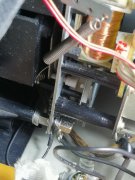
The problem is that, originally (as you can see in the below picture), the mech block was attached with the two upper corner screws directly at front panel and then the two lower corners screws were attached to some L-shaped wings to a base plate with the AMTS spring and then the base plate was screwed to the base chassis.
This (very stupid) situation caused a torque stress to the main mech plate (and then quite a lot of W&F towards the end of cassette sides) , due mostly to a couple reasons: the quite strong AMTS spring which pushes the cassette against the mechanism when you close the cassette door, through the rubber/metal plate they named AMTS, and also the point that the mech is attached a bit on the front panel and a bit to the base chassis which aren't so solidly secured themselves, then i.e. you put a deck stacked on the AIWA and it also stresses the mech the same way as the AMTS plate/spring!
For a few years, I was forced to regularly open the deck and bend back a bit those "L shaped" wings but the solution was short lived and I had to repeat it regularly.
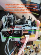
03_Mech attachment_Orig.jpg

At some point, I tried to find a definitive solution to this stupid designing mistake: attaching the mech block to the front panel only!
Then, I've cut those L-shaped wings from the base AMTS support (which is still needed to stay in the deck because of the AMTS spring) and noticed the lower corner (plastic) mounting posts at front panel were just there but they were a bit shorter, to make some room for that stupid L-shaped thing.
So, i've found a way to make those posts longer, to reach the lower corners of the mech block and re-attached the mech to the front panel only!
Also added some ground wires because, in original shape, the mech attached to the base chassis got the gnd from there.
Problem solved!
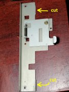
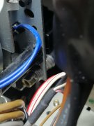
04_Mech attachment mod_1.jpg


05_Mech attachment mod_2.jpg


06_Mech attachment mod_3.jpg


Then, of course, I've applied a few mods to the electronics to make the new amorphous heads work properly (details later).

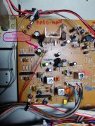
And, since I was there, I also replaced all the electolytic capacitors... and, while doing that, I've found out that on this model (I own two AD-F880 and both have the same factory error!) there is one polarized electrolityc capacitor which is reverse biased by about 7 volts (!!!) due to a wrong print on the PCB...
It happens that this capacitor is there to filter a -7 VDC (minus seven) line and they put the negative of the cap to gnd and the positive of the cap to the -7 VDC.
But, being a negative supply, you have to put the positive of the cap to the gnd and the negative to the (negative) supply, otherwise it's reverse biased!
Of course, I've put the replacement capacitor the proper way.
07_Reversed EL-CAP.jpg


will continue on next post...
 

vince666

Chief Journeyman
Joined
May 15, 2013
Messages
1,053
Location
deep south of Italy
Tagline
I will not be missed! :p
#2
Now, after the needed mods to solve issues and the "quality" mods (such as ANT's ones) and the ones to make the new AX head working fine, a quick (teaser) review about what I call the "versatility" mods, all about the recording side.

I've re-purposed the MPX filter button/switch to be able to record type2 tapes at 120us EQ, to improve treble saturation limits of the tapes.
Then, I've cut the PCB tracks going to the MPX filter button and joined some of the other sides of the cut tracks to simulate a situation where the MPX filter is always off (i never used MPX filter because I don't record from FM radio).

So, on the back/solder side of the mainboard, one "way" of the MPX switch simply switches the PB EQ to 120us while the other way of the switch applies a correction REC EQ filter to get the proper recorded response while the PB EQ is set to 120us... all of this works while the deck is in type2 mode, when you insert a type2 tape (the PB at 120us would work also with type4 tape, though, but only the PB side).
The transistors are used as switches, here, thanks to another mod by Alex/ANT (needed on original AD-F880 but not in this "AX heads" version) which was very useful to understand how to use transistors as switches in this deck!

08_CrO2 switch 70-120_1.jpg


09_CrO2 switch 70-120_2.jpg


10_CrO2 switch 70-120_3.jpg


11_CrO2 switch 70-120_4.jpg


Then, I've re-purposed a couple more switches I never really used... the "timer" and the "memory" switches... now they became 3 position "bias ranges" switches for ferric and chrome modes.
It means that, with these switches, I did make the actual range of the front panel "bias fine" knob quite larger, since the bias fine knob depens also on the range I choose from the selectors.
Also, I can free-up some of the strict dependency of the bias settings between the Ferric, Chrome and Metal modes, so that I can freely choose how to set the bias fine range for the Ferric and Chrome tape types.

Last, since I had to re-do the REC EQ filters completely, because of these new AX amorphous heads, and the new filters needed more parts than originally fit in the mainboard, I had to add/insert a few extra DIY small PCBs with the new filters on.

But, I've went even further!
I've added yet another PCB (placed vertically on the mainboard) with extra REC EQ filtering options, triggered by transistor switches, so that I have a switch (added on front panel by making a suitable hole!) which makes me choose 3 different REC EQ settings, respectively for the 3 tape types.
The TOTL model AIWA XK-009 actually has a REC EQ switch with low, mid, hi settings... then I've made something similar but choosing the REC EQ filters without following what they made on the XK-009 but by thinking about what I'd like to get myself.

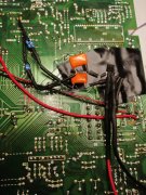
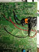
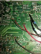
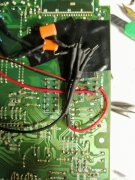
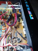
Some pictures of all these small PCBs added onto the mainboard.


12_added PCBs.jpg


13_REC EQ switch.jpg


14_vertical PCB supports.jpg


15_vertical PCB.jpg


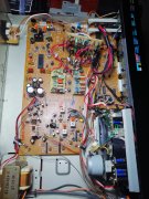
here below, the mainboard with all the add-ons assembled back in the deck.

16_assembled.jpg


17_assembled_2.jpg


will continue on next post...
 

vince666

Chief Journeyman
Joined
May 15, 2013
Messages
1,053
Location
deep south of Italy
Tagline
I will not be missed! :p
#3
and this is how the deck now looks about from the front panel.
(must re-print the stickers at the print shop here below, because the black background in my home printer is more dark grey than proper black, but this is a minor cosmetic thing I will do at a later time).


deck is still missing the cassette door with AMTS system and, at lower right in the picture, you can spot the timer and memory switches re-purposed to bias range switches.

18_Front panel (left side).jpg


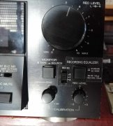
here, you can spot the mpx filter button re-purposed to record type2 tapes at 120us EQ and also the new REC EQ switch I've added where I can choose 3 different REC EQ settings.

19_Front panel (right side).jpg


now, finally, a few measurement plots to show you what actually happens with these "versatility" mods...
all of these measurement examples were taken on a 1988-89 SONY UX-PRO tape.

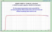
this is source mode at -20dB VU in the deck (which is equal to -40dB FS in the plots).

20_SOURCE MODE.jpg


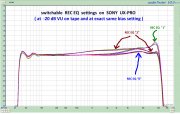
here below, the 3 different REC EQ settings on the UX-PRO tape, without touching the bias at all... all the frequency response differences are due only to the REC EQ.
There is the setting "0" which would be the most proper for this tape, then the setting "1" where there is about 1dB of boost on the high frequency area (useful for those tapes which might need some help on treble) , last there is the setting "2" which adds about 1dB of boost mostly in the mids area and which might be useful for those tapes with a drop in the mids area, i.e. oldschool dual coated pure chromdioxid tapes or also the metal tapes made for chrome position (That's EX , EM-X , CD-MH ... Denon HD8... and the likes).

21_UX-PRO_EQ modes.jpg


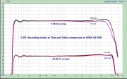
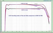
here below, a comparison between the (usual) 70us and the 120us modes on the same UX-PRO tape.
I've made plots at -20dB VU , at 0dB VU and at +6dB VU for both 70us and 120us EQ modes, to put in evidence how things change in regards of treble saturation.

As you can easily see, recording at -20dB VU doesn't really show any meaningful difference, because we are far enough from treble saturation even at the standard 70us EQ setting (same happens at -10dB VU , maybe even because of some help from HX-PRO, then I didn't add the plot at -10dB VU).

But... the more you record louder, the more the 120us EQ setting gets an advantage over the 70us EQ setting.... very easy to spot in the FR curves at 0dB VU and even more evident at +6dB VU.

The 120us EQ setting means you have a "more open" Playback response (then also some more hiss) but, on the REC side, you need to apply less treble boost.... the result is that the tape gets less stressed in the treble area.
Of course, in this situation, we are trading some more hiss on the PB side (because of the 120us setting on playback) with a better treble performance on the recording side.... which is what they did since early 80's on pre-recorded cassettes made on chrome tape at 120us EQ.


22_UX-PRO_EQ 70 and 120 at -20 and 0dB.jpg


23_UX-PRO_EQ 70 and 120 at 0 and +6dB.jpg


Of course, as soon as I will put my data and schematics in good order, I will finally add more details to this thread.

For now, it's just a teaser about what I've made on this deck, now renamed into AD-F880-MAX (M stands for Modified and AX for amorphous AX heads... but it's also nice to think I am maybe pushing this deck to the MAX :p ).

Actually, there is just one thing I wasn't still able to do.... and it's to find the proper way to boost the max bias current to properly exploit also metal tapes... point is that amorphous heads need more bias than permalloy heads and with bias trimpots just set to the max, I'd still need some more bias to properly exploit metal tapes.
This kind of modification was quite easy on an older deck (Technics RS-M260) which doesn't have any HX-PRO but, here in the AIWA, there is the HX-PRO circuit then what worked on the older deck doesn't just work here... and the whole bias oscillator + HX PRO circuit is a bit too complex for my poor brain to really understand how to do that.

So, if any of you happens to have any ideas about how to squeeze more bias current on this deck, please, let me know.


Cheers,

Vince
 
Last edited:

20tajk7

Chief Journeyman
Joined
Jul 26, 2011
Messages
837
Location
Absurdy, new name of France
Tagline
You never have too much tapedecks ^^
#5
Very well done modifications Vince !
As I remember that AX head is used in Technics RS-B85 and RS-M253X.
For the HX-PRO take a look to the µPC1297CA datasheet.
 

vince666

Chief Journeyman
Joined
May 15, 2013
Messages
1,053
Location
deep south of Italy
Tagline
I will not be missed! :p
#6
That is a very extensive rework of your Aiwa, Vincent. It's worth me looking at the thread in more detail but judging by the frequency plots your work was worth it.

Nando.
Indeed! It all started with ANT's mods several years ago... then the new heads which forced me to study this deck's schematic with care... and while doing things, new ideas happened to arise then it was just a matter of adding yet another modification after the other... to the point of this sort of "frankenstein" deck! :p

Very well done modifications Vince !
As I remember that AX head is used in Technics RS-B85 and RS-M253X.
For the HX-PRO take a look to the µPC1297CA datasheet.
yes, should just be those Technics models with these AX heads on.

Nice tip there, thanks! :)
Somehow, i had not thought to check the HX-PRO chip datasheet... will do it just now!

https://panda-bg.com/datasheet/1181-036188-UPC1297CA-NEC.pdf

Luckily, the REC EQ filters I've made on metal tape mode would be just OK if I can add some more bias than how the deck is able to do... so that, after squeezing some more bias current for the metal tapes, I won't be forced to re-make the REC EQ filters too.

About HX-PRO, I had given a good read at this nice article (shared here at ANT's website):

http://www.ant-audio.co.uk/Tape_Recording/Library/HX_Pro.pdf

The article is nice and explains how HX-PRO works (and it was useful for me to understand that my attempt to boost bias current as I had just made on the Technics RS-M260 failed just because of the HX-PRO control over the bias current) but it's not sufficiently detailed to actually tell me what to do.... I hope the above datasheet might show me any useful hints. :)
It would be a last mod to add to this deck which would make it just OK also on metal tapes which, at now, can be exploited quite about you can do on permalloy heads or a hair more, but not as much as amorphous heads can usually do.

Cheers :)
 

vince666

Chief Journeyman
Joined
May 15, 2013
Messages
1,053
Location
deep south of Italy
Tagline
I will not be missed! :p
#7
Thinking out loud about HX-PRO matter and how to boost the bias current...

Noticeing that this deck's HX-PRO circuit isn't based on µPC1297CA but they use a few NJM4560S op-amps, etc... as shown in the zone of the schematic just below the Dolby encoder chip IC3.

In the past, while modifying my Technics RS-M260, where I've put amorphous heads in place of its original sendust heads and also needed to boost the bias current, being a deck without HX-PRO where the bias current level stays constant just as you set it, it was sufficient to raise the value of a small capacitor (like 150 pF which I raised to 250 pF) just before the head and this did the trick just nicely.
After all, there are some oldschool decks where I've also seen that the bias current levels get tuned just by variable capacitors rather than by variable resistors.

Here, a while ago, I had tried to do the same (IIRC by raising the value of C401 by adding 100 pF capacitor in parallel) but nothing apparently changed then the trick didn't work.


24_REC and BIAS schematic.jpg

Then, while reading the nice HX-PRO article (mentioned in my previous post) , if I've got it right, it happens that the HX-PRO circuit (which dynamically controls the actual bias current level going to the REC head) sort of keeps into consideration the actual bias setting, the incoming high frequency level which is going to be recorded (and which would act like a sort of bias and then causing some treble self-erasure effect just while recording) and it controls the bias level through a VCA so that the "pseudo-bias" due to the incoming audio signal's high frequency and the actual bias current level coming from the bias oscillator are kept at a constant total level. (anyways, if you give a look at the aforementioned HX-PRO article, everything is explained a lot better than how I can do here!)

If I remember, and since I was directly measuring the bias current voltages going to the REC head even without sending any audio signal to the deck's inputs (so that HX-PRO had no reason to reduce the bias level going to the REC head) , the actual bias voltages going to the REC head were the same with or without raising the value of C401 capacitor.

Another thing I had tried was to change the values of the bias tuning trimpot SFR401 and the R411 attached to it (copying the same values as in the XK-009 which has amorphous heads by factory)... this appeared to give me a little more bias (measuring the voltage at the test point near the REC head) but the whole circuit seemed to become unstable, then I put things back in original shape to avoid to risk damaging it.

My best (wild) guess is that, since there is an HX-PRO circuit involved, the whole REC bias handling situation is quite more complex than on a deck without HX-PRO and then, to boost the bias current, some kind of mod should be performed just "inside" the HX-PRO, by altering the way it decides how much "total" bias must be sent to the REC head....

At the very least, I think I should read that HX-PRO article once again with great care and see if it can help finding some proper ideas, unless someone who just knows how to do it happens to suggest a proper solution.

Anyways, the bias current boost is needed only to be able to push metal tapes to their own limit... not just a strict need here, since I just own a few decks which can do a great job in exploiting metal tapes and, after all, this deck is just able to give the other tape types all the bias they need.


Cheers,

Vince
 
Last edited:

Makymak

Journeyman
Joined
Dec 6, 2021
Messages
223
Location
Where the sun meets the rocks and the sea
#8
Don't know if the RS-B965 manual be any useful to you. It has both the permalloy and the amorphous head circuits and electronics description (and so does the actual pcb!).Maybe, tracing the deferences between the two versions you can find a way to increase bias current on a similar setup.
 

vince666

Chief Journeyman
Joined
May 15, 2013
Messages
1,053
Location
deep south of Italy
Tagline
I will not be missed! :p
#9
Don't know if the RS-B965 manual be any useful to you. It has both the permalloy and the amorphous head circuits and electronics description (and so does the actual pcb!).Maybe, tracing the deferences between the two versions you can find a way to increase bias current on a similar setup.
That's a good point, indeed!
I've noticed they mention parts values for both permalloy and amorphous heads in the B965's SM... they would be surely useful to put amorphous heads just there in the B965 (something I will do sooner or later).
Anyways, the B965 with amorphous heads has also the super bias (bias at double frequency) and, even if a given head might prefer a certain bias frequency, if I understood it correctly, to set a different bias frequency while hoping it works fine, you'd need to replace the small transformer in the bias oscillator because those devices are tuned to a specific frequency and I fear this kind of parts are unobtanium (unless you can take the right one from another deck).

Also, here in the AD-F880, you can easily spot a couple tuneable coils/transformers just there in the HX-PRO circuit ( L411 and L412 on the other channel)... service manual doesn't give any hints about how to tune these but I've found around how to tune them (service manuals of some other similar AIWA models do mention how to tune them) and tuned them too... the bias current levels didn't boost, after tuning those variable coils/transformers, but it's better if they are well tuned anyway... and when you replace the head such things indeed need to be checked and, if needed, also tuned.
 

vince666

Chief Journeyman
Joined
May 15, 2013
Messages
1,053
Location
deep south of Italy
Tagline
I will not be missed! :p
#10
a good new!

I was able to boost max bias by about 6% which is enough to fully exploit a few metal tapes i tried (Sony Metal ES , Metal XR and Esprit IV) but maybe also a few more... anyways, my metal tapes are almost all Sony's then it's OK this way!

Today, i've read again (and with more care) the above HX-PRO article shared by Alex/ANT on his website (link is above at my post #6).
The answer was just there in the article!

On a deck without HX-PRO it's a lot easier, because you simply find a way to boost bias current sent at REC head and you're done.

When there is HX-PRO involved, this method just doesn't work, at all.
To explain it quickly (better if you read the article, of course) , they noticed that the treble in the sound you're recording do work like if they are some added bias to the REC head... so, the HX-PRO reduces the bias coming from the oscillator so that, together with the "bias" from the treble in the audio, their sum is constant.
So, the HX-PRO continously reads how much bias you have just at REC head.... some of this bias is from the oscillator, some is from the treble in the source you're recording... and if you are recording with no input signal, the bias at the REC head is totally taken from the bias oscillator, you add input signal containing treble and the HX-PRO reduces the bias from the oscillator but the total is kept constant.

It's clear now, the reason why my attempt to boost bias at REC head didn't work!
Basicly, i raised the bias (i.e. like i would do on a deck without HX-PRO) and the HX-PRO automatically reduces it... funny, eh? :p

Now, in this situation, it seems you cannot even set a certain bias level coming from the oscillator because HX-PRO would change it dynamically, depending on the kind of sound you feed at deck's inputs.
But, actually, there is a reference voltage (it's DC but it's a control voltage) which sets the actual level the HX-PRO refers to, as the constant level of bias to keep at REC head which is the sum of the oscillator bias and the "bias" from the treble in the input signal.
Then, the trick here is to just change the reference DC voltage.
This DC voltage is what is handled, i.e., by the bias fine knob and, of course, by the bias trimpots on the mainboard.
I had just handled this DC voltage while making the "bias ranges" mod... but I had not tried anything on it to try to raise the max DC voltage and then the max reference voltage the HX-PRO refers to.

So, without even removing the mainboard from the deck, I simply added a parallel resistor onto R413 and it worked.
I had tried adding a few different values in parallel to R413... i tried 470K , 390K, 100K and also putting a piece of wire to bring R413 to zero.
I noticed that I got the most boost of max bias current at REC head with 390K in parallel on that R413 (which is 100K)... so i brought that R413 from 100K to about 80K.... and the actual max bias current I could set (measured at REC head) got boosted by about 6%... better than nothing because it just makes a difference... i.e. i've gained about 1.5dB of MOL on the Sony Esprit IV which is around +10.5 dB VU now, while the mid 80's Sony Metal ES now shows a MOL of almost +13dB VU (maybe +12.7 or so)... I'd say I can be just happy this way. :):cool:

25_REC and BIAS schematic.jpg

Now, I can finally close the chassis of this deck! (which was kept open for way too long time. o_O )

Cheers,

Vince
 

Alex SE

Journeyman
Joined
Oct 10, 2021
Messages
278
Location
Sweden
Tagline
Amateur
#17
Looking at those plots I would rather call it AD-F880SF (SF = Sci-Fi)
Besides how good FR and rec are I just dont get it how did you get almost 100% equal channels.
Nomatter what and how I do on my deck (you know which one) there is no way I can make L & R be so equal as on your plots. Did a tests (& adjustments) with TDK SA, Maxell UDII-CD, TDK D, BASF FE-I
Just admire your work.
 

vince666

Chief Journeyman
Joined
May 15, 2013
Messages
1,053
Location
deep south of Italy
Tagline
I will not be missed! :p
#18
Looking at those plots I would rather call it AD-F880SF (SF = Sci-Fi)
Besides how good FR and rec are I just dont get it how did you get almost 100% equal channels.
Nomatter what and how I do on my deck (you know which one) there is no way I can make L & R be so equal as on your plots. Did a tests (& adjustments) with TDK SA, Maxell UDII-CD, TDK D, BASF FE-I
Just admire your work.
Nice one about Sci-Fi :D

Equal channels? Well, other than taking care of carefully match parts for equal tolerances between the channels (especially in the REC EQ filters and PB EQ amp) , it was a matter of painfully fine tuning while trying LOTS of different cassettes, finding the best "average" fine tuning.
Of course, not any cassettes will deliver such equal channels... there are mechanical tolerances in the cassette shells, of course.
 

vince666

Chief Journeyman
Joined
May 15, 2013
Messages
1,053
Location
deep south of Italy
Tagline
I will not be missed! :p
#20
It is obviously that you have to much time Vince (joking)
Very good and interesting work
Thanks, my friend. :)

Truth is that this modification project was made, little by little, during a few years.
But, yes, in total it needed just a lot of time. :D

and the reason why I did it was that this AD-F880 had a quite worn head and I had just amorphous to replace it but, at the same time, amorphous is my own preference.

another deck where I had put amorphous heads (the original ones were sendust heads) is my Technics RS-M260, which is a simplier and more oldschool design... also in this case I've managed to make some different switchable REC EQ settings.
 
Top