400 Series 1 Build

Hexis22

Chief Journeyman
Joined
Dec 28, 2022
Messages
730
Location
Wisconsin
#1
Taking on another 400 project for member @Hinodit to go along with his existing full WOPL 700B.

This will be a complete rebuild and include the following main components:
- Full WOPL (Caps, Regulator, Control board, Backplanes, Outputs)
- LED lighting
- New chassis
- Isolated transformer bolts
- Speaker output DC Protection
- New RCA inputs
- New AGC fuse holders

The donor amp was in very clean condition with only minor cosmetic scratches. All output drivers are original date matched XPL909's.

These amps are like a box of chocolate, you just never know what you have until you dig in and open them up. SIL pads on outputs and extruded heat sinks are a welcome sight, NO thermal grease to deal with.

Both rail fuses were 35V 14A...


Hexis22

Chief Journeyman
Joined
Dec 28, 2022
Messages
730
Location
Wisconsin
#3
Tear down begins for harvesting required OE parts to supplement White Oak components.

Components used from the original amp consist of the following:
- Faceplate and meters
- Heat sinks
- Cap cradle and clamp
- Transformer
- Copper RCA grounding plate
- Aluminum P-Clamps for Bias transistors


Vintage 700b

Chief Journeyman
Joined
Mar 13, 2019
Messages
803
Location
Wisconsin
Tagline
Fabricator
#6
Taking on another 400 project for member @Hinodit to go along with his existing full WOPL 700B.

This will be a complete rebuild and include the following main components:
- Full WOPL (Caps, Regulator, Control board, Backplanes, Outputs)
- LED lighting
- New chassis
- Isolated transformer bolts
- Speaker output DC Protection
- New RCA inputs
- New AGC fuse holders

The donor amp was in very clean condition with only minor cosmetic scratches. All output drivers are original date matched XPL909's.

These amps are like a box of chocolate, you just never know what you have until you dig in and open them up. SIL pads on outputs and extruded heat sinks are a welcome sight, NO thermal grease to deal with.

Both rail fuses were 35V 14A...


Super Clean 400 to start with, another beauty.
Will be another fantastic WOPL when you are done Eric !!!
 

Hexis22

Chief Journeyman
Joined
Dec 28, 2022
Messages
730
Location
Wisconsin
#9
Control board assembly completed following the sequence documented within the White Oak BOM, smallest profile components to largest.

PCB cleaned with 99% Isopropyl Alcohol to remove solder flux remnants, inspected under magnification for solder joint integrity, and removal of stray solder balls and debris.

If using Phoenix connectors, solder 3 place connectors on the bottom side before placing tall electrolytic caps.

Also ensure the 3 place connector wire openings point down towards larger Phoenix connectors.

All power resistors spaced above PCB surface for improved airflow around the components and help prevent PCB heat discoloration (based on good assembly practice, not because the power rating was undersized).


Last edited:

Hexis22

Chief Journeyman
Joined
Dec 28, 2022
Messages
730
Location
Wisconsin
#10
Backplane boards assembled, cleaned with 99% Isopropyl Alcohol, and inspected under magnification.

Components installed in the following order:
- Socket cups for TO-3 outputs with OFP facing component side of PCB
- PEM nuts - use TO-3 mounting bolts and springs to hold in place while soldering
- Low profile resistors and diodes
- Fuse holders
- Test points
- Capacitors - spaced off the board to prevent Red coating from interfering with solder joints

All components leads trimmed below the PEM nut surface on solder side of PCB to eliminate potential for shorting to housing while mounted.


Joined
May 17, 2023
Messages
307
Location
Finland via the deep south
Tagline
Details, details
#12
Heat sink fins cleaned, modified, and ready for mounting.

- All TO-3 mounting holes drilled out with a letter "C" drill to aid in alignment with holes in housing
- All holes chamfered (both sides) with a 82 degree countersink to eliminate sharp edges and prevent shorts through sil pads


Attention to detail...nice work, Eric
 

mlucitt

Veteran and General Yakker
Joined
Jun 24, 2011
Messages
3,494
Location
Jacksonville, FL
#13
Heat sink fins cleaned, modified, and ready for mounting.
Eric, I do the same type of Heat Sink prep, I also chamfer the holes in the chassis, it makes it easier for the Nylon shouldered spacers to go in the punched holes.

I must say the alignment of the Chassis and Heat Sinks in the WOA Model ONE is perfect. I have an old set of Vermont Gage, pin gages. The 0.2420" gage passes through all 12 rear Chassis holes on each Heat Sink when it is held in alignment. I just had to check... Pin Gages.jpg
 
Last edited:
Joined
May 17, 2023
Messages
307
Location
Finland via the deep south
Tagline
Details, details
#14
Eric, I do the same type of Heat Sink prep, I also chamfer the holes in the chassis, it makes it easier for the Nylon shouldered spacers to go in the punched holes.

I must say the alignment of the Chassis and Heat Sinks in the WOA Model ONE is perfect. I have an old set of Vermont Gage, pin gages. The 0.2420" gage passes through all 12 rear Chassis holes on each Heat Sink when it is held in alignment. I just had to check...
I did the same (well, not align them with gauge pins...) for all of my heat sink holes (didn't think of doing the chassis but the bushings went in just fine), had to rig up something to do the transistor side as I didn't have a L-O-N-G shank chamfering tool but turned out nicely.
 

Gepetto

Administrator
Staff member
Joined
May 15, 2011
Messages
14,035
Location
Sterling, MA
Tagline
Old 'Arn Enthusiast
#15
Eric, I do the same type of Heat Sink prep, I also chamfer the holes in the chassis, it makes it easier for the Nylon shouldered spacers to go in the punched holes.

I must say the alignment of the Chassis and Heat Sinks in the WOA Model ONE is perfect. I have an old set of Vermont Gage, pin gages. The 0.2420" gage passes through all 12 rear Chassis holes on each Heat Sink when it is held in alignment. I just had to check...
But of course Mark, Amada laser cut precision.
 

mlucitt

Veteran and General Yakker
Joined
Jun 24, 2011
Messages
3,494
Location
Jacksonville, FL
#16
I did the same (well, not align them with gauge pins...) for all of my heat sink holes (didn't think of doing the chassis but the bushings went in just fine), had to rig up something to do the transistor side as I didn't have a L-O-N-G shank chamfering tool but turned out nicely.
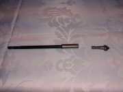
This is my go to tool every time I do a chassis.
Chamfering Tool and Extension.jpg
 

Hexis22

Chief Journeyman
Joined
Dec 28, 2022
Messages
730
Location
Wisconsin
#17
Eric, I do the same type of Heat Sink prep, I also chamfer the holes in the chassis, it makes it easier for the Nylon shouldered spacers to go in the punched holes.

I must say the alignment of the Chassis and Heat Sinks in the WOA Model ONE is perfect. I have an old set of Vermont Gage, pin gages. The 0.2420" gage passes through all 12 rear Chassis holes on each Heat Sink when it is held in alignment. I just had to check... View attachment 78601
I hope those bulk caps with bus bars laying on top in the background are fully discharged...


Hexis22

Chief Journeyman
Joined
Dec 28, 2022
Messages
730
Location
Wisconsin
#20
Housing assembly started.

- Installed RCA inputs using isolation washers on both sides of the housing to ensure copper ground plate isolated from chassis ground
- No internal lock washers under lower backplane 4-40 mounts to ensure good thermal conduction between heat sinks/housing to Q6 Bias transistors
- Backplane boards mounted within chassis
- Q6 Bias transistors soldered to backplane board after installation into chassis to ensure proper height and orientation for minimizing stress on the TO-92 leads
- 22 AWG leads to Control board tie wrapped together to minimize stress on solder joints during assembly

Also note, the original power supply "gull wing" cap clamp will not easily work with new White Oak capacitors due to smaller diameter of new caps. It could be manipulated to work, but I plan to use the aluminum plate supplied with the WO kit to secure caps to the cradle.

Unfortunately, I did not realize this until after mounting the transformer to the housing. I had to remove the transformer and mount a bolt from the underside of the cradle before reassembling.


Last edited:
Top