20tajk7
Chief Journeyman
- Joined
- Jul 26, 2011
- Messages
- 1,040
- Location
- Absurdy, new name of France
- Tagline
- You never have too much tapedecks ^^
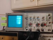
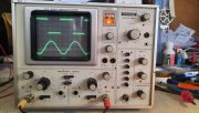
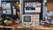
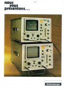
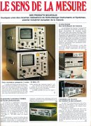
The story of my first oscilloscope, a 1975 Schlumberger CRC5043,
bought in 2009, I was beginner in electronics back then and didn't even had BNC cables ! also preferred using the B input as the A had some contact issues.
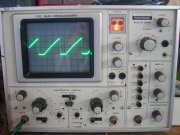
Used a lot for testing audio equipment and some experiments with oscillators but it went bad in 2010.
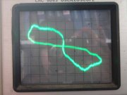
Never managed to draw that while playing with the XY mode !
No manual available at time and less experience, read a lot of threads of several forums about electronics were guys suggested to replace all electrolytic capacitors.
Replaced them but the "8" was still here and still not found any manual, except a dude in a French forum who wanted to sell me a copy done with an inkjet printer for 150€ ! so I left the unit it in the basement in the "unfixable shelf".
Then came across an ebay auction in 2015 with a working CRC5043, a probe and the original service manual for less than 100€.
Works better than the first one, but it also went bad after a year of light use (got an Hameg HM-203 and use it as a main scope) but thank to schematics it was an easy fix (+64V rail turned to -6V due to some bad diodes).
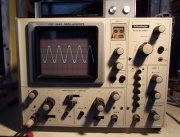
Sometimes I took the first one out of the basement trying to fix it, with the service manual and now more experience in electronics I've found out that the LM723 regulator of the +12V rail were dead, goes the +21V instead.
But the +12V rail is reference for the other power supply rails so that raised all others and messed up the whole unit.
Followed the manual that said to power up the unit with the vertical & horizontal boards removed to check the voltages, not good at all, the tube gets all green and very luminous ! almost broke the wall outlet while unplugging !
Plugged the boards back, luminosity is too high so I had to mess with focus to not burn the tube, back to the "unfixable shelf" for some years.
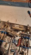
Put a new LM723, +12V and -12V are back but the +64V is too low and +135V is too high and the luminosity is still too high.
Needed to find a way to measure the high voltage going to the tube (+3kV and -1.1kV).
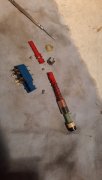
Used a cheap method by making a more or less 11x attenuator with a 10MOhms resistor in series with a cheap multimeter with 1MOhms input impedance.
Tested with a 5kV electric fence generator, didn't get shocks and seen 400V pulses, seems to be fine, after testing with mains voltage it appears to have 11.4x of attenuation.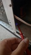
In action, makes nice sparks.
High voltage was too high, almost +4500V and -2200V, that's why luminosity was too high.
That was due to a shorted transistor in the high voltage regulation loop.
Also two open capacitors in the -1100V rail, maybe due to the over voltage.
Also found another open capacitor and two dead transistors in the +135V area.
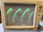
Replaced these bad components and now I got a trace !
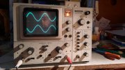
Took me almost 13 years !
Now I need to fix the bad contacts of the vertical amp & time base switches.
bought in 2009, I was beginner in electronics back then and didn't even had BNC cables ! also preferred using the B input as the A had some contact issues.

Used a lot for testing audio equipment and some experiments with oscillators but it went bad in 2010.

Never managed to draw that while playing with the XY mode !
No manual available at time and less experience, read a lot of threads of several forums about electronics were guys suggested to replace all electrolytic capacitors.
Replaced them but the "8" was still here and still not found any manual, except a dude in a French forum who wanted to sell me a copy done with an inkjet printer for 150€ ! so I left the unit it in the basement in the "unfixable shelf".
Then came across an ebay auction in 2015 with a working CRC5043, a probe and the original service manual for less than 100€.
Works better than the first one, but it also went bad after a year of light use (got an Hameg HM-203 and use it as a main scope) but thank to schematics it was an easy fix (+64V rail turned to -6V due to some bad diodes).

Sometimes I took the first one out of the basement trying to fix it, with the service manual and now more experience in electronics I've found out that the LM723 regulator of the +12V rail were dead, goes the +21V instead.
But the +12V rail is reference for the other power supply rails so that raised all others and messed up the whole unit.
Followed the manual that said to power up the unit with the vertical & horizontal boards removed to check the voltages, not good at all, the tube gets all green and very luminous ! almost broke the wall outlet while unplugging !
Plugged the boards back, luminosity is too high so I had to mess with focus to not burn the tube, back to the "unfixable shelf" for some years.
Put a new LM723, +12V and -12V are back but the +64V is too low and +135V is too high and the luminosity is still too high.
Needed to find a way to measure the high voltage going to the tube (+3kV and -1.1kV).
Used a cheap method by making a more or less 11x attenuator with a 10MOhms resistor in series with a cheap multimeter with 1MOhms input impedance.
Tested with a 5kV electric fence generator, didn't get shocks and seen 400V pulses, seems to be fine, after testing with mains voltage it appears to have 11.4x of attenuation.

In action, makes nice sparks.
High voltage was too high, almost +4500V and -2200V, that's why luminosity was too high.
That was due to a shorted transistor in the high voltage regulation loop.
Also two open capacitors in the -1100V rail, maybe due to the over voltage.
Also found another open capacitor and two dead transistors in the +135V area.
Replaced these bad components and now I got a trace !

Took me almost 13 years !
Now I need to fix the bad contacts of the vertical amp & time base switches.

