700B Build

Hexis22

Chief Journeyman
Joined
Dec 28, 2022
Messages
554
Location
Wisconsin
#1
Started a new 700B build for a member looking for help on upgrades.

This build will be no holds barred and include the following main components:
- Full WOPL (Control board, Backplanes, Outputs, Caps, Regulator)
- LED lighting
- Chassis and Faceplate
- Isolated transformer bolts
- Knobs
- Speaker output DC Protection
- New RCA inputs

The donor amp was in relatively good condition with quite an assortment of replacement outputs and a great overall starting point.

The chassis was tweaked and minor repairs performed in the past (Output drivers, Speaker output binding post, Fuses, AC plug), including thermal paste on all 4 pre-drivers!!


Vintage 700b

Chief Journeyman
Joined
Mar 13, 2019
Messages
758
Location
Wisconsin
Tagline
Fabricator
#2
Now you're talking !!!
Enjoy this build, looks like a clean start .....and good old thermal paste !
Cleaning all of that off the fins etc. is my least favorite part of the build.
 

Hexis22

Chief Journeyman
Joined
Dec 28, 2022
Messages
554
Location
Wisconsin
#10
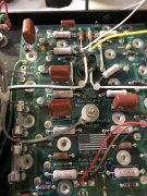
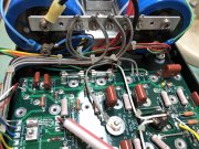
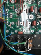
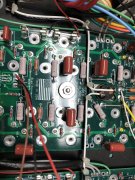
I have a question regarding preferred AC wire routing on 700B amps. I'm contemplated with respect to placing all AC wires across the middle of the backplane boards, or run AC along the top (Perry's method).

Here are my initial thoughts:

Top placement
- Greater seperation between AC and most other components
- AC closer to sensitive RCA and Control board Op Amp input circuits

Middle placement
- Potential for AC coupling to greater number of surrounding components and wiring
- Greater distance to sensitive input signals

Or, if you route AC in and out wiring closely together it makes little difference...
 
Last edited:

Vintage 700b

Chief Journeyman
Joined
Mar 13, 2019
Messages
758
Location
Wisconsin
Tagline
Fabricator
#11
I have a question regarding preferred AC wire routing on 700B amps. I'm contemplated with respect to placing all AC wires across the middle of the backplane boards, or run AC along the top (Perry's method).

Here are my initial thoughts:

Top placement
- Greater seperation between AC and most other components
- AC closer to sensitive RCA and Control board Op Amp input circuits

Middle placement
- Potential for AC coupling to greater number of surrounding components and wiring
- Greater distance to sensitive input signals

Or, if you route AC in and out wiring closely together it makes little difference...
Hello,
I have always run my AC on top, and DC on the bottom, but the dual heat sensors in the middle must then have the two drop downs, which I went through the center vertically and branched (hope that makes sense). I did it this way, because the power switch wiring/Triac also fit well into that piece of real estate, and that AC wiring can also be run with the senser wires. It gets tight, about as tight as I want to see it. I have three 700b's done this way, and they are very quiet, no 60hz hum and no issues. I see you have Joe's chassis for your build. That should give you the extra space for cleaner routing. That little extra is a blessing on a 700b.
Your work is impeccable, so I am sure your end plan will be very well thought out and I look forward to seeing how much you enjoy this build. I will be away for about a week, so won't be able to monitor, but please keep posting your progress. What happened to that 700 SII you were starting? I think you have caught the WOPL Build Fever bad......:D......I know I have !!!!! It is addicting.
Have a great week!
 

George S.

Veteran and General Yakker
Joined
Feb 18, 2020
Messages
4,645
#12
If you go across the middle, there's plenty of room to raise the AC wires away from the back planes.
Using a original 700 chassis, I spaced my control board out a additional 1/2" from factory and the AC run is well off the back planes across the center.
I built my 400's with AC over the top, then retrofit them with AC across the center. No discernible change in noise, none, just a black hole of silence.
Don't think it really matters. Hopefully Joe will comment.
Personally, I think it's easier to build across the center and uses less wire, important for many first time builders.
I'd build with regard to Triac placement.
 

Hexis22

Chief Journeyman
Joined
Dec 28, 2022
Messages
554
Location
Wisconsin
#13
Thanks for the feedback, I forgot about the potential of mounting a Triac in the center between the thermal switches.

My 700 S2 build was put on hold to shorten turnaround time on this customer build.
 

Gepetto

Administrator
Staff member
Joined
May 15, 2011
Messages
13,595
Location
Sterling, MA
Tagline
Old 'Arn Enthusiast
#14
I have a question regarding preferred AC wire routing on 700B amps. I'm contemplated with respect to placing all AC wires across the middle of the backplane boards, or run AC along the top (Perry's method).

Here are my initial thoughts:

Top placement
- Greater seperation between AC and most other components
- AC closer to sensitive RCA and Control board Op Amp input circuits

Middle placement
- Potential for AC coupling to greater number of surrounding components and wiring
- Greater distance to sensitive input signals

Or, if you route AC in and out wiring closely together it makes little difference...
IMG_5441.JPG IMG_2043.JPG IMG_2034.JPG IMG_2033.JPG
 

Gepetto

Administrator
Staff member
Joined
May 15, 2011
Messages
13,595
Location
Sterling, MA
Tagline
Old 'Arn Enthusiast
#15
The best results can be achieved running midships as pictured above. The key is keeping AC as far away from the control board front end as possible. The bottom half of the control board doesn't care as it is tied in via the global feedback. You just want to avoid having the AC field interpreted as an input signal and then amplified. That can happen if you get too close to the sensitive front end. With the WOA chassis, you are provided longer standoffs for the control board as the chassis is deeper and allows that. That fact buys you more separation. Midships also gets you the shortest possible AC wire runs and allows you to break out the runs to the front power switch between the 2 midplanes as pictured above. Sorry for the dust in a couple of pictures, maid's day off :)
 

Hexis22

Chief Journeyman
Joined
Dec 28, 2022
Messages
554
Location
Wisconsin
#17
Isolating the transformer bolts using nylon stepped washers and packing tape.

The transformer cradle and new chassis must be drilled out for clearance to allow installation of nylon washers. This required filling the cradle with JB Weld in all 4 corners to support new hole diameter.

New grommets installed into cradle as well.


Hexis22

Chief Journeyman
Joined
Dec 28, 2022
Messages
554
Location
Wisconsin
#18
Made some measurements after mounting the transformer to find proper AC connection.

Following Joe's instructions (re-posted below), I found the primary winding closest to the core and farthest from the secondary to reduce coupling in hopes of lowering the noise floor. The AC Line (Black) will be connected to this side of the primary.
  1. Put your DMM on the VAC scale
  2. DMM lead 1 to secondary center tap, other secondary wires left floating
  3. DMM lead 2 to safety ground of your mains plug
  4. Shunt across your DMM with 100K ohm resistor to provide a light load to the transformer coupling effect
  5. Connect L and N to the primaries in one direction. Take measurement
  6. Flip the L and N to the primaries to get the other direction. Take measurement
  7. The lowest measurement is the orientation that you want to use.


Top