How about a capacitor discussion?

8991XJ

Chief Journeyman
Joined
Oct 8, 2011
Messages
1,228
#82
I know what diagram you are looking for but I didn't grab that one from the older catalogs. I did make a list of the color used on the caps, though.

Thought I would drop the obsolete to new list along with the color code list. First from Nichicon, second from the product sheets a couple years ago. Some may have different colors. UKL changed from light blue/black to black/white, for example.
 

Attachments

vince666

Chief Journeyman
Joined
May 15, 2013
Messages
1,080
Location
deep south of Italy
Tagline
I will not be missed! :p
#83
One thing I've noticed....a lot of polystyrene in phono stages....gotta be good to use there...
good polystirene ARE good.

problem is they do exist only of very small values, up to nanofarards, then they can be used mostly for capacitance loading and for EQ network.

also, from latest post by Alex, I've learnt there are the ones made with tin foil (best) and the ones made with aluminium foil.
 

vince666

Chief Journeyman
Joined
May 15, 2013
Messages
1,080
Location
deep south of Italy
Tagline
I will not be missed! :p
#84
I know what diagram you are looking for but I didn't grab that one from the older catalogs. I did make a list of the color used on the caps, though.

Thought I would drop the obsolete to new list along with the color code list. First from Nichicon, second from the product sheets a couple years ago. Some may have different colors. UKL changed from light blue/black to black/white, for example.
I started buying UKL like 3 years ago and I've always got them black/white, though.
 

Alex SE

Journeyman
Joined
Oct 10, 2021
Messages
283
Location
Sweden
Tagline
Amateur
#85
I made a list of caps for a second 965. Wasn't 100% sure about some caps so I'll go for polarized for power supply (UPV, UPW, FM or FR), will choose some audio grade polarized for signal path and some bipolars (UES) where it's obvious a bipolar would fit better. I mean, how wrong I can do :)

I know what diagram you are looking for but I didn't grab that one from the older catalogs. I did make a list of the color used on the caps, though.

Thought I would drop the obsolete to new list along with the color code list. First from Nichicon, second from the product sheets a couple years ago. Some may have different colors. UKL changed from light blue/black to black/white, for example.
Thanx for files. I was thought that have saved that "picture" from their website but I didn't. Feel myself as a moron :( Even more crazy is that that picture cant be found anywhere.
 

vince666

Chief Journeyman
Joined
May 15, 2013
Messages
1,080
Location
deep south of Italy
Tagline
I will not be missed! :p
#91
as a rule of thumb, I am following this kind of recipe when choosing capacitors...

the ones in the signal path (i.e. coupling ones, connected in series throughout the signal path) will be bipolar ones (i.e. Nichicon UES or Panasonic SU BP).

the ones around the signal path which aren't connected in series into the signal path but they don't have a pin directly connected to the ground (and being subjected to some DC on the other pin) and also the ones at the negative feedback or around the dolby chips will be Nichicon UKL.

the ones which are clearly taking care of filtering the ripple out of the power supply, which are typically connected in parallel between some DC line/track and gnd (included the ones attached to the V+ / V- / GND of op-amps and dolby chips) will be Panasonic FM or other quality low impedance/low ESR ones (i.e. Nichicon UPW or UPM)... same goes, of course, for the bigger ones in the main power supply area of the deck/device.

Don't know if mine are the best choices or not... anyways, I've just recapped a few decks doing just this way and they all work just fine.

At a first/quick look at your pdf file, it seems you are following, more or less, these same criteria.

Cheers,

Vince
 

vince666

Chief Journeyman
Joined
May 15, 2013
Messages
1,080
Location
deep south of Italy
Tagline
I will not be missed! :p
#92
to identify a bit better what any capacitors are doing, I use to do this way...

first, I print the whole schematic on big enough size (i.e. selecting that feature on Acrobat which makes me print on many A4 sheets which then I do cut and paste together, rebuilding a very big printed schematic)... then, with a few coloured pencils, I do mark the schematic tracks... i.e. one colour for PB path, another for REC path, another for Rec Bias path, another for V+ DC, another for V- DC, and another one for the GND...
At this point, with all these tracks coloured, it will be a piece of cake to see where/how exactly any capacitors are connected.

Btw, these Technics decks are even easier because they clearly mark/label the various paths just on the schematic, then it's more doable to directly work on the pdf file on the computer screen.
 
Last edited:

Alex SE

Journeyman
Joined
Oct 10, 2021
Messages
283
Location
Sweden
Tagline
Amateur
#93
as a rule of thumb, I am following this kind of recipe when choosing capacitors...

the ones in the signal path (i.e. coupling ones, connected in series throughout the signal path) will be bipolar ones (i.e. Nichicon UES or Panasonic SU BP).

the ones around the signal path which aren't connected in series into the signal path but they don't have a pin directly connected to the ground (and being subjected to some DC on the other pin) and also the ones at the negative feedback or around the dolby chips will be Nichicon UKL.

the ones which are clearly taking care of filtering the ripple out of the power supply, which are typically connected in parallel between some DC line/track and gnd (included the ones attached to the V+ / V- / GND of op-amps and dolby chips) will be Panasonic FM or other quality low impedance/low ESR ones (i.e. Nichicon UPW or UPM)... same goes, of course, for the bigger ones in the main power supply area of the deck/device.

Don't know if mine are the best choices or not... anyways, I've just recapped a few decks doing just this way and they all work just fine.

At a first/quick look at your pdf file, it seems you are following, more or less, these same criteria.

Cheers,

Vince
Hello Vince,
Didn't wanted to bother you, I know you are up to something else. As you say, just to make it simpler.
In a signal path:
- Bipolars when in series and between two 0V
- Standard or audio when grounded or/and where there is some (positive or negative)
In power supply standard caps if other is not defined by a manufacturer.

In 965, there are 5 bipolars in a power supply C807, C808, C867, C858 and C905 and IARC some on a motor PCB which belongs to power supply too.
There are no bipolars in a signal path so leaving it as is (I mean just replace with new polarized) is OK, putting some bipolars can make it better, but putting bipolars on a wrong place...

So, things that are not clear for me are:
- Signal generator for calibration, whole that area should be treated as a signal path but at the same time, that part is not relevant for a sound. Putting standard (FR, FM, UPV...) will do just fine?
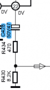
- What would you use for C426? It is on 0V, not directly connected to the ground, but it is grounded thru a R430.
1683995952296.png and here C76 1683996972901.png

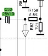
- What for C30? 0V, not directly but grounded thru a R62. I think here can be applied rule "in series and not grounded". Correct?
1683996510330.png

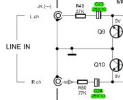
- When we say 0V, does it means absolutely 0V, not 0.5V? For example on inputs, 0V means no signal. If you send a signal to a input, say 0.5V. It means that only polarized caps should be used there? C23/C24 on the picture below. I have marked them green (as bipolars) but now when I thinking, it sounds wrong.
1683996747060.png

I believe, for the moment that's all that makes me confused.
 

Attachments

vince666

Chief Journeyman
Joined
May 15, 2013
Messages
1,080
Location
deep south of Italy
Tagline
I will not be missed! :p
#94
will give it a good look to your above pieces of schematic just after dinner.
just, more than saying between two "zero volts", i'd say in series along the signal path which is not DC but some voltage alternating with the signal itself.
Regarding dolby chips (and op-amps too) , I use to download their own datasheets so that I can see which pins are doing what, unless it's just clear from the deck's schematic.

stay tuned, my friend.... will reply in more detail later. ;)
 

Alex SE

Journeyman
Joined
Oct 10, 2021
Messages
283
Location
Sweden
Tagline
Amateur
#95
...I print the whole schematic on big enough size...
I'm doing the same on A3 (thanx to a company I'm working for)

i.e. one color for PB path, another for REC path, another for Rec Bias path, another for V+ DC, another for V- DC, and another one for the GND...
PB is more or less a piece of a cake.
REC too.
Bias is unknown field for me on schematics (I know you're have a big eyes now). I know a little about what bias is doing but not enough.
I understand V+/V- and know how to follow it on schematics.
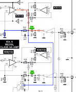
And generally, sometimes when it comes to some crossing, I can be confused. For example, on a picture below.
- Which part a blue lines belongs?
- IC5 is amplifying a signal, nothing strange. 1683998274668.png
 

vince666

Chief Journeyman
Joined
May 15, 2013
Messages
1,080
Location
deep south of Italy
Tagline
I will not be missed! :p
#96
Hello Vince,
Didn't wanted to bother you, I know you are up to something else. As you say, just to make it simpler.
In a signal path:
- Bipolars when in series and between two 0V
- Standard or audio when grounded or/and where there is some (positive or negative)
In power supply standard caps if other is not defined by a manufacturer.

In 965, there are 5 bipolars in a power supply C807, C808, C867, C858 and C905 and IARC some on a motor PCB which belongs to power supply too.
There are no bipolars in a signal path so leaving it as is (I mean just replace with new polarized) is OK, putting some bipolars can make it better, but putting bipolars on a wrong place...

So, things that are not clear for me are:
- Signal generator for calibration, whole that area should be treated as a signal path but at the same time, that part is not relevant for a sound. Putting standard (FR, FM, UPV...) will do just fine?
- What would you use for C426? It is on 0V, not directly connected to the ground, but it is grounded thru a R430.
View attachment 75785 and here C76 View attachment 75789

- What for C30? 0V, not directly but grounded thru a R62. I think here can be applied rule "in series and not grounded". Correct?
View attachment 75787

- When we say 0V, does it means absolutely 0V, not 0.5V? For example on inputs, 0V means no signal. If you send a signal to a input, say 0.5V. It means that only polarized caps should be used there? C23/C24 on the picture below. I have marked them green (as bipolars) but now when I thinking, it sounds wrong.
View attachment 75788

I believe, for the moment that's all that makes me confused.
for all of those you show here in this post, including C426 and C76 (including the same ones at the other channel) I would go with bipolars.
I see you also go with polarized for audio, which I never happened to buy till now because I directly go with bipolars in such situations, though.
 

20tajk7

Chief Journeyman
Joined
Jul 26, 2011
Messages
866
Location
Absurdy, new name of France
Tagline
You never have too much tapedecks ^^
#97
to identify a bit better what any capacitors are doing, I use to do this way...

first, I print the whole schematic on big enough size (i.e. selecting that feature on Acrobat which makes me print on many A4 sheets which then I do cut and paste together, rebuilding a very big printed schematic)... then, with a few coloured pencils, I do mark the schematic tracks... i.e. one colour for PB path, another for REC path, another for Rec Bias path, another for V+ DC, another for V- DC, and another one for the GND...
At this point, with all these tracks coloured, it will be a piece of cake to see where/how exactly any capacitors are connected.

Btw, these Technics decks are even easier because they clearly mark/label the various paths just on the schematic, then it's more doable to directly work on the pdf file on the computer screen.
I've done that when I needed to troubleshoot a muting on an Alpage AL-300, that's how I've discovered the test oscillators where always on and interferes with the playback amp (400Hz and 10kHz spikes on spectrum during playing without tape).
 

vince666

Chief Journeyman
Joined
May 15, 2013
Messages
1,080
Location
deep south of Italy
Tagline
I will not be missed! :p
#98
I'm doing the same on A3 (thanx to a company I'm working for)


PB is more or less a piece of a cake.
REC too.
Bias is unknown field for me on schematics (I know you're have a big eyes now). I know a little about what bias is doing but not enough.
I understand V+/V- and know how to follow it on schematics.
And generally, sometimes when it comes to some crossing, I can be confused. For example, on a picture below.
- Which part a blue lines belongs?
- IC5 is amplifying a signal, nothing strange. View attachment 75790
of course, you know I am not too expert in these matters... but on a crossing like that, I'd expect the signal goes to all the tracks together.
anyways, since the purpose is to just identify what the electrolytic capacitors are doing, in this specific case you have to worry only about C19 and C20 which are both in series on the signal path, then bipolars as you just marked them.

anyways, a print of a whole schematic on A3 sheet is still way too small... on Adobe Acrobat's print options you can choose to print as a poster (at least this is how they say on the italian language version of the software) and, at that point, you will be able to print the schematic on as many A4 sheets as you wish (depending on how you set the size) and it's wise to also give at least 10 mm of overlapping between the sheets, which will be useful to align them properly. It's a bit tricky, though, but doing this way I was able to print schematics also on up to 16 sheets of A4 size and after cutting/pasting them together I've got a huge sheet.
 

vince666

Chief Journeyman
Joined
May 15, 2013
Messages
1,080
Location
deep south of Italy
Tagline
I will not be missed! :p
#99
I've done that when I needed to troubleshoot a muting on an Alpage AL-300, that's how I've discovered the test oscillators where always on and interferes with the playback amp (400Hz and 10kHz spikes on spectrum during playing without tape).
yes, getting the whole schematic on a big sheet of paper where you can also write on is useful to also troubleshoot or to simply study the schematic to make modifies.
 

Alex SE

Journeyman
Joined
Oct 10, 2021
Messages
283
Location
Sweden
Tagline
Amateur
of course, you know I am not too expert in these matters... but on a crossing like that, I'd expect the signal goes to all the tracks together.
anyways, since the purpose is to just identify what the electrolytic capacitors are doing, in this specific case you have to worry only about C19 and C20 which are both in series on the signal path, then bipolars as you just marked them.

anyways, a print of a whole schematic on A3 sheet is still way too small... on Adobe Acrobat's print options you can choose to print as a poster (at least this is how they say on the italian language version of the software) and, at that point, you will be able to print the schematic on as many A4 sheets as you wish (depending on how you set the size) and it's wise to also give at least 10 mm of overlapping between the sheets, which will be useful to align them properly. It's a bit tricky, though, but doing this way I was able to print schematics also on up to 16 sheets of A4 size and after cutting/pasting them together I've got a huge sheet.
Not one A3, one page on A3 and then put them all together. My eyes are almost 50 yo, A4 wouldn't do a job :)

Regarding capacitors, what you are saying is that in case as on the left side (A) its ok to put a bipolar, and polarized have to bi used only in a case as on the right side (B)? Of course, we are talking about 0V (or less than +/-1V)
1684009438992.png
 
Top