No more 60 Hz hum in a PL2000 preamp.

mlucitt

Veteran and General Yakker
Joined
Jun 24, 2011
Messages
3,494
Location
Jacksonville, FL
Joe do you have a preference of audio quality in film capacitors if size/lead spacing is not an issue?
Of the various dielectrics - ceramic, polyethylene terephthalate (PET)/Mylar/polyester, polypropylene (PP), polycarbonate (PC), polyethylene naphthalate (PEN), Polyphenylene Sulfide (PPS), Polytetrafluoroethylene (PTFE), polystyrene (PS); or the various construction types - paper in oil, copper/aluminum film, metalized film, does one stand out?
For audio we don't need self-healing. But better ESR/ESL? Is it all just snake oil?
I found a chart that seems to show PPS (red) as the best for audio...
Plastic-Film-Dielectric-Characteristics.png
 

Gepetto

Administrator
Staff member
Joined
May 15, 2011
Messages
14,035
Location
Sterling, MA
Tagline
Old 'Arn Enthusiast
Joe do you have a preference of audio quality in film capacitors if size/lead spacing is not an issue?
Of the various dielectrics - ceramic, polyethylene terephthalate (PET)/Mylar/polyester, polypropylene (PP), polycarbonate (PC), polyethylene naphthalate (PEN), Polyphenylene Sulfide (PPS), Polytetrafluoroethylene (PTFE), polystyrene (PS); or the various construction types - paper in oil, copper/aluminum film, metalized film, does one stand out?
For audio we don't need self-healing. But better ESR/ESL? Is it all just snake oil?
I found a chart that seems to show PPS (red) as the best for audio...
View attachment 72726
If it fits, PP by all means
 

George S.

Veteran and General Yakker
Joined
Feb 18, 2020
Messages
5,034
I tend to use the Panasonic ECW series of polypropylene with crimped leads when available. Research showed most preferred WIMA polypro, with ECW a close second. Wish smaller in size and lower voltage were widely available. ECW will fit where a WIMA would be preferred, but not fit.
 

Gepetto

Administrator
Staff member
Joined
May 15, 2011
Messages
14,035
Location
Sterling, MA
Tagline
Old 'Arn Enthusiast
I tend to use the Panasonic ECW series of polypropylene with crimped leads when available. Research showed most preferred WIMA polypro, with ECW a close second. Wish smaller in size and lower voltage were widely available. ECW will fit where a WIMA would be preferred, but not fit.
Agree, WIMA is the top of the heap, Pana does a very reasonable second. I specify Pana for the power decoupling on the backplanes because they are top side repairable if necessary. WIMA has that drawback.
 

George S.

Veteran and General Yakker
Joined
Feb 18, 2020
Messages
5,034
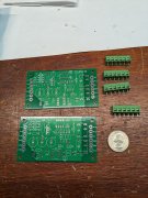
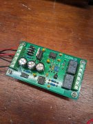
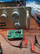
Ordering parts to build 2 of Pete Millet's automatic mute boards to quash the turn on and off thumps. These should in theory work well.
Also looking at adding output caps to the preamps rear channels. Appears PL overlooked this. May have to mount them on the foil side due to space issues.
Want to get the PL2000 S2's set up for thump free 4 channel. Those Phoenix Contact Connecters are extra 3 screw units from WOPL building. They snap together to make 6 screw units and fit the boards perfectly.
 

Attachments

e30m3mon

Chief Journeyman
Joined
Feb 9, 2013
Messages
876
Location
Hudson Valley NY
Tagline
---
Ordering parts to build 2 of Pete Millet's automatic mute boards to quash the turn on and off thumps. These should in theory work well.
Also looking at adding output caps to the preamps rear channels. Appears PL overlooked this. May have to mount them on the foil side due to space issues.
Want to get the PL2000 S2's set up for thump free 4 channel. Those Phoenix Contact Connecters are extra 3 screw units from WOPL building. They snap together to make 6 screw units and fit the boards perfectly.
You go, George! Looking forward to this next upgrade phase.
 

George S.

Veteran and General Yakker
Joined
Feb 18, 2020
Messages
5,034
Been doing some A/B listening with two PL2000 preamps that are very similar except for output caps. One was recently upgraded to 22uF TDK Polyethylene Terephthalate (PET) caps and the other has the old upgraded 4.75 uF Panasonic ECW Polypropylene (PP) caps.
I immediately heard a increase in bass with the TDk's, but overall, I prefer the Panasonic's. They're just smoother and sweeter listening, less fatiguing. After much searching, 4.75 uF is the largest value In this form factor and series i can find and will fit, May try to parallel some of these in the future.
Going to fire up the irons and pull those TDK.
 

George S.

Veteran and General Yakker
Joined
Feb 18, 2020
Messages
5,034
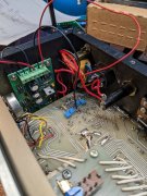
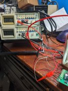
Installed a Pete Millet muting board into the 2000. In mock up it pulls 10-20 mA as it cycles from startup to idle . Immediate thought was "oh crap, this is going to a problem". Sure is a issue. I have the rails set to 16 VDC. The muting board pulls the rails down to 2 VDC! Time to read and learn about upgrading the transformer. Luckily I have a extra original transformer to test and measure. Should help me figure out what I need to make this work.
 

Attachments

George S.

Veteran and General Yakker
Joined
Feb 18, 2020
Messages
5,034
Tap it into the raw voltage before your dropping resistors and separately rectify it and filter it. You don't want that crap on your op amp rails
That's what I did, except took it after the voltage dropping resistors as I could temporarily tack it to the pads for testing. Thought was those resistors wouldn't make a huge difference.
After lunch I'll try it above the resistors. Thanks.
 

Attachments

grapplesaw

Veteran and General Yakker
Joined
Aug 13, 2014
Messages
2,778
Location
Vancouver
Tagline
---
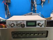
George I built a Sound Card Interface / AC RMS voltmeter from Pete Millett a few years ago. used it with computer for out put, spectrum analysis and cross hatch distortion measurements. He has really good designs.
I do not use it now that I have an Audio Precision. So if anyone is interested I’ll let it go.

Pete says: 8CF8A2CB-619A-443F-9507-464FA7AF5992.jpeg 58457B29-8B45-4874-BA16-21CEF4E6BE78.jpeg
Most of us DIY audio types have been using PC sound cards to make measurements. There are excellent, inexpensive programs available to do test and measurement of audio equipment available. Personally I use Audiotester. If you've been around my web site you've seen FFT plots generated that way.

What has always been lacking is a decent interface between the sound card and the device under test (DUT for you geeks). There has been much discussion in forums like DIYaudio about this, and many proposals and circuits shown, but so far I've not seen anything implemented.

The problem with sound cards is that they are designed for fixed line-level inputs and outputs. Depending on the card this may be between 1V and 5V RMS maximum. They are also not tolerant of overloads - accidentally deliver 20V into your sound card input and you will most likely be looking for a new sounds card.

The other issue I have with sound cards is one of calibration. I know it is possible to calibrate the levels, but I have not had very good luck doing it. So, unless you have some other type of voltmeter, it's hard to get an absolute level measurement from a sound card. This is important for many things, like measuring the output power of an amplifier.

So what we need is a magic box with the following characteristics:

  • Able to accept a wide range of voltages and scale them for the sound card input
  • Survive overvoltage inputs without damage
  • Provide AC-coupling to protect from DC voltages (like plate voltage on a tube stage)
  • Provide a reasonably high impedance input, preferably with some ability to make floating measurements
  • Buffer and amplify the sound card output, with very low distortion and low output impedance
  • Provide a calibrated true-RMS AC voltage measurement
 

George S.

Veteran and General Yakker
Joined
Feb 18, 2020
Messages
5,034
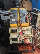
So, I'm getting 26 VAC output from the transformer, above the dropping resistors, across the secondary legs, and 13 VAC from each leg to the center tap. So all good there.
Soldered a wire above each dropping resistor, and ran them to the mute boards to power it at 26 VAC.
Board "boots" and runs through it's countdown with the blinking LED, and idles pulling about 115 mA.
Rail voltage is now 2 VDC. No good.
I tested the board in a DC configuration last night on a power supply. At 6 VDC, the board pulled between 10-20 mA on "boot", and idled at 20.
I looked at the LM2940CT 5 VDC linear regulator data sheet last night and saw the graph showing draw increases with voltage. Verified this by increasing VDC and watching the increase in mA.
Considering adding a simple 120/6 VAC transformer to power the board.
What do you all think?
 

Attachments

grapplesaw

Veteran and General Yakker
Joined
Aug 13, 2014
Messages
2,778
Location
Vancouver
Tagline
---
So, I'm getting 26 VAC output from the transformer, above the dropping resistors, across the secondary legs, and 13 VAC from each leg to the center tap. So all good there.
Soldered a wire above each dropping resistor, and ran them to the mute boards to power it at 26 VAC.
Board "boots" and runs through it's countdown with the blinking LED, and idles pulling about 115 mA.
Rail voltage is now 2 VDC. No good.
I tested the board in a DC configuration last night on a power supply. At 6 VDC, the board pulled between 10-20 mA on "boot", and idled at 20.
I looked at the LM2940CT 5 VDC linear regulator data sheet last night and saw the graph showing draw increases with voltage. Verified this by increasing VDC and watching the increase in mA.
Considering adding a simple 120/6 VAC transformer to power the board.
What do you all think?
Hate to ask this but if you change the range on your meter does that 2 volt change reading
 

George S.

Veteran and General Yakker
Joined
Feb 18, 2020
Messages
5,034
Nope, auto ranges. 200 Volt setting in the photo. Now hooking up my spare transformer and try to learn more about it and it's limitations. Outputs exactly 34 VAC with no load.
Under load of the preamp only, no mute board, 26 VAC. The "JOYS" of a unregulated power supply!
 

George S.

Veteran and General Yakker
Joined
Feb 18, 2020
Messages
5,034
Think I've figured it out. Going to try voltage dropping resistors on both AC feed wires to the mute board. If I can get the voltage low, the current draw will be low. The trick will be doing it without having the voltage drop out.
If this isn't possible, then looks like upgrading the original transformer to one with a higher VA power rating and no voltage drop out would be the ticket.
Think I'll listen to a album and try this tomorrow.
 

e30m3mon

Chief Journeyman
Joined
Feb 9, 2013
Messages
876
Location
Hudson Valley NY
Tagline
---
Out of curiosity, Sniff makes a PS regulator board for the C1. Could that be used in the 2000, with the appropriate voltage regulators ( I don’t recall the circuit volt requirement for either chassis) installed?
 

George S.

Veteran and General Yakker
Joined
Feb 18, 2020
Messages
5,034
Out of curiosity, Sniff makes a PS regulator board for the C1. Could that be used in the 2000, with the appropriate voltage regulators ( I don’t recall the circuit volt requirement for either chassis) installed?
Thought about it. The 1000 S2 uses a regulation circuit .
Mark L. used to comment that a unregulated power supply could respond faster than a regulated supply.
I'm trying to keep it simple as possible. Simplest would have been just installing a output grounding switch with a couple 200 ohm resistors in line. But I saw this mute board with the automatic timers. Thought it was very cool.
Main reason for pursuing this is I have a really nice Class A Bipolar power amp I need to protect from inadvertent turn on thump. Blew 3 opamps out on a Asus Xonar Essence sound card last time it happened. Lucky it didn't get the preamp or speakers.
 

George S.

Veteran and General Yakker
Joined
Feb 18, 2020
Messages
5,034
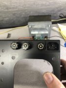
No joy. Pulled the supply dropper resistors out for maximum rail voltage. With 100R droppers on the mute board supply it just barely works properly at 4 VAC, pulls 58 mA. would rather have it at 6-12 VAC. Rail voltage drops to + and - 8 VDC, really would like + and - 16 VDC. No good with the stock transformer. Going to look for a better transformer.
 

Attachments

Top