Mark, got it, will rework it. Not sure if the thump changed or not. Thanks!George, my brain knew what I was saying, but it did not come out correctly.
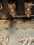
Just as in the PL700 amps, the input 220K resistor that bleeds the DC-blocking capacitors goes to Ground on the input jacks.
For PL2000, the 4.7M resistor has to bleed the caps to Ground. The Ground trace on the back of the circuit board is a handy place. I don't think it matters which side of the cap is bled off, I would choose the upstream or, circuit-facing lead because that would likely be the source of any DC voltage that is blocked by the capacitor.
Did the turn on thump get louder with the larger 22uF caps? Those caps can store plenty of volts, but the current is very small.

You are using an out of date browser. It may not display this or other websites correctly.
You should upgrade or use an alternative browser.
You should upgrade or use an alternative browser.
No more 60 Hz hum in a PL2000 preamp.
- Thread starter George S.
- Start date
Turn your preamp on first and then your amp. The DC protect has a built in delay that should mask this
grapplesaw
Veteran and General Yakker
Hi George
I am late to this thread. I have not fully studied the schematic but do these output caps you are changing , C50 and C49, effect outputs levels at various frequencie?
my understanding is changing the capacitance can alter both bass and High freiquency. So my query is what is the deciding factor on making these value changes Or I missing something In what you have done. Just curious
glen
Improves low frequency response and lowers output impedance of the preamp across the board.Hi George
I am late to this thread. I have not fully studied the schematic but do these output caps you are changing , C50 and C49, effect outputs levels at various frequencie?
my understanding is changing the capacitance can alter both bass and High freiquency. So my query is what is the deciding factor on making these value changes Or I missing something In what you have done. Just curious
glen
grapplesaw
Veteran and General Yakker
Loking at what you have now is a film capacitor replacing the two 22uf electrolytic caps on each channel. So filtering points not changed but you have decided that the film caps pass the signal better is that it? Would a bypolar 22uf electrolitic not be as good?
grapplesaw
Veteran and General Yakker
Joe as there is no resistor tied to these caps they are not a high pass filter. What is function called.I’d like to find a calculator for seeing the changes with different cap value. Look at several preamps from carver and phase linear 22uf seams to be the standard for these output caps in the signal path. I’m pretty green when it comes to these out put caps.Improves low frequency response and lowers output impedance of the preamp across the board.
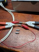
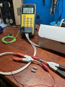
The PL2000 used two polarized 2.2 uF 50V caps in series just before each output jack. I tend to just throw the old parts in small boxes for each project, so still have these originals.
They're measuring 1.34 uF in series at 120 Hz. Was using 4.75 uF Panasonic ECW, Mark L. recommend the 22 uF TDK.
They're measuring 1.34 uF in series at 120 Hz. Was using 4.75 uF Panasonic ECW, Mark L. recommend the 22 uF TDK.
Attachments
grapplesaw
Veteran and General Yakker
Thanks GeorgeThe PL2000 used two polarized 2.2 uF 50V caps in series just before each output jack. I tend to just throw the old parts in small boxes for each project, so still have these originals.
They're measuring 1.34 uF in series at 120 Hz. Was using 4.75 uF Panasonic ECW, Mark L. recommend the 22 uF TDK.
the service manual was not clear and looked like 22uf back to back. Anyway what you have done is a 10 fold increase in this capacitor. do you know how to calculate what that dos to impedance and any kind of filtering of the sound path. It’s in the sound path so just increasing it is not the same as increasing a power cap. What I’m trying to get is what is the purpose of these caps? Dc blocking?
I found this to be an interesting statement
“caps that are used for coupling a signal and blocking DC (or simply as a safety measure should DC ever become present) perform no 'energy storage' at all, other than accidentally. The AC presented to one side of the cap is coupled through to the other side, and if the cap is large enough (compared to frequency and circuit resistance), it will never have any appreciable voltage across it. With no voltage, there is no stored energy. There will always be a tiny voltage present, but it's generally small enough to be ignored”
Glenn, I'm simply going on what Joe has recommended for these units. My understanding is they are primarily DC blocking caps, but also affect frequency and impedance.
If I could fit a 44 uF in there, I would give it a go based on what Joe has said and the huge output film caps found in high end preamps. Wish I could be more help, but I'm more of a mechanic than a engineer.
If I could fit a 44 uF in there, I would give it a go based on what Joe has said and the huge output film caps found in high end preamps. Wish I could be more help, but I'm more of a mechanic than a engineer.
grapplesaw
Veteran and General Yakker
Me to budGlenn, I'm simply going on what Joe has recommended for these units. My understanding is they are primarily DC blocking caps, but also affect frequency and impedance.
If I could fit a 44 uF in there, I would give it a go based on what Joe has said and the huge output film caps found in high end preamps. Wish I could be more help, but I'm more of a mechanic than a engineer.
I remember he once said "well behaved preamps don't need large DC blocking caps" on the outputs".
If you pull up a Acurus preamp schematic you won't see them on the outputs, they use a 10 uF coupling cap there, and 1000 uF caps on the + and - 18 VDC rails.
But the Acurus is line stage, and the old Carver products aren't. Think I've seen big output caps on older Marantz products.
If you pull up a Acurus preamp schematic you won't see them on the outputs, they use a 10 uF coupling cap there, and 1000 uF caps on the + and - 18 VDC rails.
But the Acurus is line stage, and the old Carver products aren't. Think I've seen big output caps on older Marantz products.
Mark L , no joy. Thump is unchanged and brutal. Going to pull those resistors out. No problem, was well worth the try. Will do more reading.
Been using the power strip to turn the whole system on at once and the DCP delay as Joe remarked saves the system from thump.
Been using the power strip to turn the whole system on at once and the DCP delay as Joe remarked saves the system from thump.
Attachments
J!m
Veteran and General Yakker
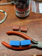
Tubing on there… I had to really zoom in to see what I was seeing…
MusicSteve
Journeyman
Joe, I use a stop watch to time out my Denon delay before it turn the outputs on. (or anything else upstream) Than I change the value of the timing Capacitor and it will increase the time it takes to turn the speaker protection board on. after everything upstream is on.Turn your preamp on first and then your amp. The DC protect has a built in delay that should mask this
This will also get rid of any unwanted buzzing if the Amp turns on first.
Merry Christmas and Happy Holidays Everybody.
")
mlucitt
Veteran and General Yakker
Sorry to hear that you have chronic thump disease. Typically, the 'thump' is a small inrush DC voltage presented to the front end of the amplifier, then amplified, and can be related to a cap charging (or discharging) at turn on (or turn off); it could also be a bad ground.Mark L , no joy. Thump is unchanged and brutal.
Does the thump manifest itself on both channels?
Can you bypass the DC Protection board to see if you get turn off thump with preamp connected? With preamp disconnected?
Could the thump be originating in the amp? With the preamp disconnected, with the amp still thump?
Because you described the thump as "brutal" it would suggest to me a turn-on spark. Normally, the small .01uF X-type or Y-type AC rated capacitor will snub this small spark. The Phase Linear amps really benefit from the addition of this cap across the power switch because of the +15 Amp surge across the contacts of the unobtainium switches. The preamps have less surge, of course, but the spark can still be present.
Now, I had a brainstorm... If your preamp is ON all the time and you use a power strip, the preamp power switch contacts are already closed and a snubber cap will have no effect. BUT, is there a cap across the switch on the power strip? That could be the source of the spark into the preamp, and ultimately into the amp.
Mark, was doing some reading last night. So explored a few things. Definitely caused by the preamp. Originally thought it was caused by the power switch, but plugging in the power cord to the preamps IEC socket with the preamp on also causes the same thump.
Not a whole lot of info on the web about this. Most threads end with informing the OP to use proper start up and shut down procedures.
No big deal. Thanks!
Not a whole lot of info on the web about this. Most threads end with informing the OP to use proper start up and shut down procedures.
No big deal. Thanks!
The popping of the preamp into the amp is a bona fide signal going from the preamp into the amp which had been powered up prior (recommend reversing that power up order since the amp has a DCP or leave your preamp on all the time). It is not power switch noise at all. It is due to the unsettled nature of the op amp behavior as the power supplies increase from zero to +/-15V. The op amps will not regulate their output until there is at least +/- 5VDC if you are using RC4136 op amps or +/- 2.5VDC if you are using OPA2134 op amps. That means that during that region below that minimum voltage the op amp is free to misbehave all it likes. Simple to understand.Mark, was doing some reading last night. So explored a few things. Definitely caused by the preamp. Originally thought it was caused by the power switch, but plugging in the power cord to the preamps IEC socket with the preamp on also causes the same thump.
Not a whole lot of info on the web about this. Most threads end with informing the OP to use proper start up and shut down procedures.
No big deal. Thanks!
Me to bud
I have been off the grid for a couple days with Christmas festivities that required my full attention to enjoy with the grandkids. I see that a lot of chatter has occurred.
It is pretty simple guys.
A 10uF blocking cap has an impedance of 1592 ohms at 10Hz, 159.2 ohms at 100Hz, 15.92 ohms at 1000Hz, 1.592 ohms at 10KHz and so on.
If you have 2 2.2uF caps in series to act as a non-polar cap, you really have a 1.1uF non-polar blocking cap.
A 1.1uF blocking cap has an impedance of 14468 ohms at 10Hz, 1446.8 ohms at 100Hz, 144.68 ohms at 1000Hz, 14.468 ohms at 10KHz and so on.
If you are happy with your preamp having an output impedance of >14K ohms at 10Hz then party on. I would not be because it is compromising all that low frequency output.
Bigger is definitely better. Why don't all manufacturers use whomping big caps? Because they cheap out. Big film caps are expensive and take up a lot of room.
Hope this explanation helps. Merry Christmas.
Last edited: