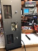
Very nice Al...I suppose this could go in any number of forums..."DIY", "What are you doing today", yada yada...advise if it needs to move. Thx
I have the D500 project near the phase of power-up, but wanted to ensure the two NOS "oil can" sized electrolytic capacitors in the PS were properly reformed. I've tried getting some background on why this is important and how to do it, also tapped Joe and Glen for their advise; I recall the PS caps I bought from Joe for my 400-II project were formed prior to him shipping.
Also took Spencer's project a few postings back as inspiration and combined the functions of reformer, discharger and decided to put the DBT circuit into this package. All-in-one kind of thing. The wooden box had some nonsensical 1970's electronic project that was tossed from the lab where I taught HVAC electrical systems. It reminded me of the kind of box that old test equipment was housed in ... back in the 70's and earlier!
The DC power supply in the background right has volts (R), power (M), and amps (L) on the front panel. It will crank up to 120VDC and 3 amps. I figured it would be a good idea to observe the amps passing through the reforming circuit, so I added a couple banana jacks for an external ammeter. Optionally I have a jumper that just completes the circuit between the jacks. The resistor can be changed out (yep - those are old PL speaker binding posts) to whatever size is needed to work with the capacitor under test. While reading documentation on how others monitored their reforming progress, measuring the amps and volts dropping over time and final values are important, so I added the meter to measure the volts across the forming resistor as well as a switch to alternatively select the volts across the test cap. If the analog volt meter does not provide enough granularity, another pair of jacks is provided for a DVM across the meter.
In discharge mode, you can observe the volts dropping in real time ... as well as observe some voltage re-charge, as larger caps often do, when the button is released.
The good news is that I got to use some parts lying around here forever, but unfortunately had to buy some other parts and then invest the time to make the panel, powder coat, etc. It was a fun diversion nonetheless.
You are using an out of date browser. It may not display this or other websites correctly.
You should upgrade or use an alternative browser.
You should upgrade or use an alternative browser.
Dual-500 king of the Castle
- Thread starter grapplesaw
- Start date
Reminiscent of the very old test equipment in wooden boxes. They were specialized tools and works of art. Nice job.I suppose this could go in any number of forums..."DIY", "What are you doing today", yada yada...advise if it needs to move. Thx
I have the D500 project near the phase of power-up, but wanted to ensure the two NOS "oil can" sized electrolytic capacitors in the PS were properly reformed. I've tried getting some background on why this is important and how to do it, also tapped Joe and Glen for their advise; I recall the PS caps I bought from Joe for my 400-II project were formed prior to him shipping.
Also took Spencer's project a few postings back as inspiration and combined the functions of reformer, discharger and decided to put the DBT circuit into this package. All-in-one kind of thing. The wooden box had some nonsensical 1970's electronic project that was tossed from the lab where I taught HVAC electrical systems. It reminded me of the kind of box that old test equipment was housed in ... back in the 70's and earlier!
The DC power supply in the background right has volts (R), power (M), and amps (L) on the front panel. It will crank up to 120VDC and 3 amps. I figured it would be a good idea to observe the amps passing through the reforming circuit, so I added a couple banana jacks for an external ammeter. Optionally I have a jumper that just completes the circuit between the jacks. The resistor can be changed out (yep - those are old PL speaker binding posts) to whatever size is needed to work with the capacitor under test. While reading documentation on how others monitored their reforming progress, measuring the amps and volts dropping over time and final values are important, so I added the meter to measure the volts across the forming resistor as well as a switch to alternatively select the volts across the test cap. If the analog volt meter does not provide enough granularity, another pair of jacks is provided for a DVM across the meter.
In discharge mode, you can observe the volts dropping in real time ... as well as observe some voltage re-charge, as larger caps often do, when the button is released.
The good news is that I got to use some parts lying around here forever, but unfortunately had to buy some other parts and then invest the time to make the panel, powder coat, etc. It was a fun diversion nonetheless.
NeverSatisfied
Chief Journeyman
Very nice job Al.
- Joined
- Jan 14, 2011
- Messages
- 75,849
- Location
- Gillette, Wyo.
- Tagline
- Halfbiass...Electron Herder and Backass Woof
Excellent!!
grapplesaw
Veteran and General Yakker
Well the bar has been raised once again. Well done Al
e30m3mon
Chief Journeyman
Thanks Glen - and all for the kind words and your support. Not my intention to raise the bar, but I got a little carried away ! Scope creep.Well the bar has been raised once again. Well done Al
We enjoyed your scope creep Al...Thanks Glen - and all for the kind words and your support. Not my intention to raise the bar, but I got a little carried away ! Scope creep.
grapplesaw
Veteran and General Yakker
So Al what news do you have for us? (It’s alive) oops let the cat out of the bag
e30m3mon
Chief Journeyman
IT'S ALIVE !So Al what news do you have for us? (It’s alive) oops let the cat out of the bag
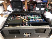
Holy shit....everything went so smoothly because of Glen's outstanding support and creating the Full Complimentary backplane for this beast! And most certainly - Kudos has to be given to Joe and his incredible technical talents to develop the WOPL control board - as well as so many other products.
I was so blown away by how things went today - I honestly did not know what to expect but certainly any outcome was possible, considering the size of this project and the number of moving parts involved. I had it all together a couple months ago but have been tied up with outdoor things, but here we are in short daylight, crappy weather days.
Many thanks thanks to Glen for his support along the development of this project. I'm still not finalized as I have to go through the bias setting procedure and a couple loose ends.
Al
Attachments
NeverSatisfied
Chief Journeyman
Welcome to the lightning club, lesser amps will run and hide from this beast, lol.
- Joined
- Jan 14, 2011
- Messages
- 75,849
- Location
- Gillette, Wyo.
- Tagline
- Halfbiass...Electron Herder and Backass Woof
Not all will....
grapplesaw
Veteran and General Yakker
Set bias at .380v volts on high Z Al after running idle for 1/2 hour or so.
NeverSatisfied
Chief Journeyman
Then they aren’t lesser amps, lolNot all will....
- Joined
- Jan 14, 2011
- Messages
- 75,849
- Location
- Gillette, Wyo.
- Tagline
- Halfbiass...Electron Herder and Backass Woof
LOL!!!!!!!!!!!!
grapplesaw
Veteran and General Yakker
I just didn’t know how to say that Spencer. Thank’s for clearing that awkward moment upThen they aren’t lesser amps, lol
Last edited:
Great work Al, hope you enjoy the hell out of it...Glen has this formula down on the D500sIT'S ALIVE !
Holy shit....everything went so smoothly because of Glen's outstanding support and creating the Full Complimentary backplane for this beast! And most certainly - Kudos has to be given to Joe and his incredible technical talents to develop the WOPL control board - as well as so many other products.
I was so blown away by how things went today - I honestly did not know what to expect but certainly any outcome was possible, considering the size of this project and the number of moving parts involved. I had it all together a couple months ago but have been tied up with outdoor things, but here we are in short daylight, crappy weather days.
Many thanks thanks to Glen for his support along the development of this project. I'm still not finalized as I have to go through the bias setting procedure and a couple loose ends.
Al
e30m3mon
Chief Journeyman
Thanks Joe ... Man, he has this nailed!Great work Al, hope you enjoy the hell out of it...Glen has this formula down on the D500s
wattsabundant
Chief Journeyman
At the risk of being labeled a butt head by critiquing a fine test set, it is desired to mount binding posts/banana jacks on 0.75" centers to accommodate adaptor plugs and test cables that use dual banana plugs.
Looks like you are back to the drawing board AlAt the risk of being labeled a butt head by critiquing a fine test set, it is desired to mount binding posts/banana jacks on 0.75" centers to accommodate adaptor plugs and test cables that use dual banana plugs.
grapplesaw
Veteran and General Yakker
Life’s a bitch ain’t it Al


