- Joined
- Jan 14, 2011
- Messages
- 75,814
- Location
- Gillette, Wyo.
- Tagline
- Halfbiass...Electron Herder and Backass Woof
Damn dude...you own stock in Keithly??

No. These are older unit made in the USA. They are good quality at a good priceDamn dude...you own stock in Keithly??
You need four and more is betterI think you need more DMM's Glen....
And like I need two AP’s as well. It’s a disease that you know all to wellI think you need more DMM's Glen....

Yes it matches the service manual. I may look for a relay to fast discharge on powerr off.Actually, this sounds like a reasonable solution -- especially if you have a sign (on the inside of the top cover / or even on top of the top cover, 'Fear This' style ) to tell anyone going in something to the effect that "Please wait 6+ minutes for lethal voltages to dissipate BEFORE proceeding."
(Preferably in stencil font -- always catches my eye/makes me stop & read for comprehension...must be my military background. :0)
This way you've more than covered the bases, safety-wise. Anyone who puts themselves within touching distance of coke can-sized caps should know that they are at risk, and should be discharging B4 proceeding...
Put a 1N4004 diode to your main capsFully powered both channels. All good but!
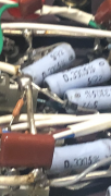
I have stopped to figure best solution for a problem I created. Having added separate power supply for constant voltage to the control board I have eliminated any built in power drain from the main caps. In other words they do not discharg. I need to add a resistor that will drain the Cap’s say over a couple of minutes but not effect overall performance of the power supply. We have 35,000 uf at 240 volt.
Anyone got a calculation for what may be best would be a help
Ok. I have them on the rails as fly back diodesPut a 1N4004 diode to your main caps
Ok added one across + & - capPut a 1N4004 diode to your main caps
Ok added one across + & - cap
No real discharge happing
fly back diodes are 1n4004. Also correctly oriented
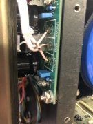
Will doHi Glen, you will have to describe your dilemma a bit more fully for me to understand and recommend. Perhaps a quick hand sketch, snap a photo of it and post it.
So removed the second power supply. Caps now discharging as I suspected when bias supplied by rails through control board. Will have leave idea for later thought