Dual-500 king of the Castle

Fully powered both channels. All good but!
I have stopped to figure best solution for a problem I created. Having added separate power supply for constant voltage to the control board I have eliminated any built in power drain from the main caps. In other words they do not discharg. I need to add a resistor that will drain the Cap’s say over a couple of minutes but not effect overall performance of the power supply. We have 35,000 uf at 240 volt.

Anyone got a calculation for what may be best would be a help
Put a 1N4004 diode to your main caps
 
Put a 1N4004 diode to your main caps
Ok. I have them on the rails as fly back diodes
I best see if I have thoughts in backwards as well

here is one on neg rail
 

Attachments

  • F20CFD6A-1AC3-4A8E-B38A-80921FA4B4C3.png
    F20CFD6A-1AC3-4A8E-B38A-80921FA4B4C3.png
    10.1 MB · Views: 23
Put a 1N4004 diode to your main caps
Ok added one across + & - cap
No real discharge happing

fly back diodes are 1n4004. Also correctly oriented
 

Attachments

  • ABF037F5-7DF0-4522-ABD0-419C624A7E9E.jpeg
    ABF037F5-7DF0-4522-ABD0-419C624A7E9E.jpeg
    1.4 MB · Views: 3
Anyway testing continues. Both channels work with low input. Time to button it up for heavy duty loads and fuses.
 
Ok added one across + & - cap
No real discharge happing

fly back diodes are 1n4004. Also correctly oriented

Hi Glen, you will have to describe your dilemma a bit more fully for me to understand and recommend. Perhaps a quick hand sketch, snap a photo of it and post it.
 
Joe the issue is the main power caps do not discharge over a few minutes. Actually hold charge for hours. Not to safe I’d say.

As a new feature I no longer take power from the main caps to the control board as it has its own power supply ( pictured sorta) tied to the the ac output of the main transformer. The reason is to have 80-0-80 constant supply voltage to the control board.
When you run off the rail for supply to the control board this voltage changes from 80-0-80 to 120-0-120. This change in voltage really only effects the Bias voltage as it gets fed from the rails. Therefore it’s not optimized for best bias voltage in one or the other rail voltage as you set it be best with high rail not low.

I have fly back diodes on both positive and negative rail of each channel. These are not discharging residual stored voltage in power caps. I added one 1n4004 across the positive and negative main cap and this did Not help to discharge them. Of coarse I can manual do it and I can also do it with pair of resistors giving a constant drain, not my desired choice.

what part of the pl700 circuit accomplish this job to discharge the caps over time. I always thought it was leakage in the control board.
I do not recall this problem on any other build only this with the second power supply which , by the way drains very quickly?
 

Attachments

  • 1706B04B-9908-4891-8281-F1EF12E0B7BB.jpeg
    1706B04B-9908-4891-8281-F1EF12E0B7BB.jpeg
    1.6 MB · Views: 18
So removed the second power supply. Caps now discharging as I suspected when bias supplied by rails through control board. Will have leave idea for later thought
 
So removed the second power supply. Caps now discharging as I suspected when bias supplied by rails through control board. Will have leave idea for later thought

I am not really following what you are attempting to do Glen...
 
My change to a separate board power supply has now been sorted out. I changed to high voltage supply windings after confirming with Joe on doing this. Thanks again Joe for being there for us.

I still get a small change in Bias but only .02v swing and this is because of residual heat difference from the rails static voltage change. Now I have .372v on high and .354v on low. I am very pleased with the out come

I have added a 15k wire wound resistor across the main caps for slow discharge when turning off. This may be replaced with a fast dump resistor and relay combo. We’ll see if that’s needed or not
 
Why are you concerned about cap voltage drain if your On delay/off relay is working?? What are you thinking here Glen?
 
So the King has new life

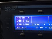
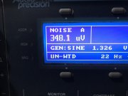
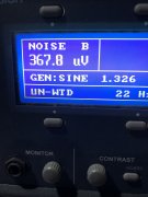
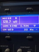
here are residual noise
A channel is left
B channel Right

1k across inputs and 8 ohm load on outputs.

two reading for each as lower numbers are at low rail and the tad higher numbers are at high rail


As well here are the other details
output each channel into 8 ohms with less that .008 N+THD 525 watts. and low 250 watts. That’s Awesome Boys

dc offset .68 Land .98R
 

Attachments

  • 53028BD8-2EB0-4023-A179-94511794E89D.jpeg
    53028BD8-2EB0-4023-A179-94511794E89D.jpeg
    2.9 MB · Views: 12
  • FE6DAF57-44DC-4AC7-8AC1-6FEB8B13DAD8.jpeg
    FE6DAF57-44DC-4AC7-8AC1-6FEB8B13DAD8.jpeg
    2.9 MB · Views: 10
  • 64F9208A-E91A-47DA-B42A-C1A28AA68A4A.jpeg
    64F9208A-E91A-47DA-B42A-C1A28AA68A4A.jpeg
    1.4 MB · Views: 10
  • 2A0326D9-2503-4B6E-8CA9-99955498818B.jpeg
    2A0326D9-2503-4B6E-8CA9-99955498818B.jpeg
    1.6 MB · Views: 9
Why are you concerned about cap voltage drain if your On delay/off relay is working?? What are you thinking here Glen?
Well it doesn’t drain without this. When you turn off supply the main power relay releases fine but due to my crazy second supply for the control board the main caps just sit there fully charged for hours without some form of drain. Any ideas other than what I have would be great. I do mot think this may be the best solution long term

I have the resistor mounted in This photo
 

Attachments

  • image.jpg
    image.jpg
    1.8 MB · Views: 14
Why is that a concern though?? BTW, Nice residual noise on that monster....
 
Why is that a concern though?? BTW, Nice residual noise on that monster....
Thanks. RN all due to Joe and his G board and some sound wire work. I did not think I get these numbers due to the transformer not having any shielding ( end Bells)

as to your comment why the concern you may be right and I have over thought it. I always have my discharge setup connected when it’s open. I’ll try it without and see if al good. It’s going to have “You’ll get zapped and Killed if you open this cover” on the top and bottom.


I think the RN is phenomenal on that beast..
 
Back
Top