
You are using an out of date browser. It may not display this or other websites correctly.
You should upgrade or use an alternative browser.
You should upgrade or use an alternative browser.
I blew out a couple output transistors on my PL400, what next?
- Thread starter rollcentre
- Start date
rollcentre
New Around These Parts
- Joined
- Mar 22, 2021
- Messages
- 48

Alright guys, I'm back at it.
It is still failing the DBT, I have a continuity tester on my DMM, which helped me isolate some things.
It seems like I'm having trouble with involving
Q15 and Q17 (if I'm reading the schematic correctly) it's the output transistors 1st column from the power trans, 1st and 2nd rows down)
View attachment 51580
View attachment 51581
I have all of the transistors socketed and screwed down except for the screws in Q15 and Q17. The transistors are there, just no screws.
It will pass a DBT like this, but when I put screws in (even loosely) for Q15 and Q17 it will fail.
I have been testing it with my continuity setting on my DMM and I'll sometimes (not everytime) I get continuity between Q15 an Q17 and the chassis when the screws are in.
I'm looking at the schematic and trying to figure out what's going on. If D14 is open, or R43 or R45 is shorted it would be shorting the positive fused supply to ground when the screws are put in. Is this correct? I guess I should quadruple check those and use my DMM instead of the multi function tester.
If that isn't it, I'll pull the heatsink off and see if the socket is damaged and shorting to the chassis.
Can you guys think of anything else I can try?
Nope, this is not valid reason for a DBT glowing...
I'm looking at the schematic and trying to figure out what's going on. If D14 is open, or R43 or R45 is shorted it would be shorting the positive fused supply to ground when the screws are put in. Is this correct? I guess I should quadruple check those and use my DMM instead of the multi function tester.
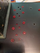
Collectors of Q15 and Q17 are directly connected to the B+ rail and the collector are the transistor cases. Recommend you take out Q11, Q13, Q15 and Q17 and then carefully from the inside slowly pull the Q15 and Q17 sockets away from the back wall and inspect the barrels of these sockets for breakage or crushing. Attached are some examples of what you may find, photos taken from my vast collection of wall art...


Also check for burrs around the holes punched in the heatsink for these 2 transistor locations. Burrs will pierce through the sil pad insulators and show up when you apply voltage to the B+ rails.
Look more closely, you have a collapsed socket wall on the uppermost Q17 screw locationI'm not seeing any damage from this side, here is a pic of what I'm seeing-
View attachment 51583
This is a pic of the Q15/Q17 sockets
rollcentre
New Around These Parts
- Joined
- Mar 22, 2021
- Messages
- 48
I think the heatsink was just a little bit misaligned, which caused the transistors to go into their sockets and the screws to go in pretty normally. The heatsink was pushed just a little too far to one side and the screw threads would just barely touch it. That's my theory anyway.
After I got the heatsink back in I noticed that, aligned it better, and now it came up fine on the DBT.
I guess now its time to proceed with bias adjustment!
Thanks for the pointers!
After I got the heatsink back in I noticed that, aligned it better, and now it came up fine on the DBT.
I guess now its time to proceed with bias adjustment!
Thanks for the pointers!
rollcentre
New Around These Parts
- Joined
- Mar 22, 2021
- Messages
- 48
I was following the bias setting instructions. Nothing plugged into the amp. Just my DMM hooked to the test points. I turned the bias pots fully CCW, let the amp warm up, 10-15 mins for good measure. Bias is at .415-ish volts on the left channel, and also .415-ish on the right channel. Pots are already fully CCW
That's a just little bit high.
That's a just little bit high.
I was following the bias setting instructions. Nothing plugged into the amp. Just my DMM hooked to the test points. I turned the bias pots fully CCW, let the amp warm up, 10-15 mins for good measure. Bias is at .415-ish volts on the left channel, and also .415-ish on the right channel. Pots are already fully CCW
That's a just little bit high.
Are you certain you put the Schottky diodes provided in the D3 location and not a standard 1N4148 diode? I cannot tell from your pictures...
rollcentre
New Around These Parts
- Joined
- Mar 22, 2021
- Messages
- 48
Are you certain you put the Schottky diodes provided in the D3 location and not a standard 1N4148 diode? I cannot tell from your pictures...
Damn Joe, you're good!
Nope, I didn't. I remember now that I accidentally populated d3 and d4 for full comp, I fixed d4, but missed d3.
- Joined
- Jun 11, 2010
- Messages
- 6,949
- Location
- Powhatan, Virginia, United States
- Tagline
- WassupYa Mang?
Hi RC. Looks like you're getting there so far. Good job Sir!
But.. @Gepetto (Joe) - Given I think this is to be a quasi setup, shouldn't he have the 411's or SJ's in the driver positions instead of the same MJ 96's that we'd use for the outputs? If not, won't that cause possible oscillations in use? Or is that a rev G driver board "feature" now?")

But.. @Gepetto (Joe) - Given I think this is to be a quasi setup, shouldn't he have the 411's or SJ's in the driver positions instead of the same MJ 96's that we'd use for the outputs? If not, won't that cause possible oscillations in use? Or is that a rev G driver board "feature" now?
rollcentre
New Around These Parts
- Joined
- Mar 22, 2021
- Messages
- 48
Hi RC. Looks like you're getting there so far. Good job Sir!
But.. @Gepetto (Joe) - Given I think this is to be a quasi setup, shouldn't he have the 411's or SJ's in the driver positions instead of the same MJ 96's that we'd use for the outputs? If not, won't that cause possible oscillations in use? Or is that a rev G driver board "feature" now?
Thank you! Yes this is a quasi comp configuration.
I have RCA 410s in the bottom row of the 2nd and 4th column (from the transformer).
rollcentre
New Around These Parts
- Joined
- Mar 22, 2021
- Messages
- 48
Joe could do a better job of explaining it but from what I understand the oscillations are more prone to the negative column (2nd and 4th) than the positive column.
rollcentre
New Around These Parts
- Joined
- Mar 22, 2021
- Messages
- 48
I think we're there guys!

Bias set at .375 both channels
I'm digging the LED board!
Bias set at .375 both channels
I'm digging the LED board!
AngrySailor
Veteran and General Yakker
- Joined
- Oct 15, 2014
- Messages
- 3,419
- Tagline
- ---not quite right
Sweet... should there be RCA 410’s across the bottom though?I think we're there guys!
View attachment 51598
Bias set at .375 both channels
I'm digging the LED board!
- Joined
- Jan 14, 2011
- Messages
- 75,839
- Location
- Gillette, Wyo.
- Tagline
- Halfbiass...Electron Herder and Backass Woof
Yes, but if you are short you can get by with 2 .
It only matters in column 2 and 4...columns 1 and 3 do no have the quasi construct in those circuits.Sweet... should there be RCA 410’s across the bottom though?
As Perry would say...Huh??Joe could do a better job of explaining it but from what I understand the oscillations are more prone to the negative column (2nd and 4th) than the positive column.
Phase Linear Pre-Driver and Driver Selection
This post is to provide a set of guidelines for selection as the sources for original devices are drying up and substitutes will have to be sought.
First let's get the definitions clear:
Pre-Drivers are classic RCA410 location. Typically Q11 and Q12 in the PL400 and the PL700B.
Drivers are the classic PL909 location. Typically Q13-Q18 in the PL400 or Q13-Q22 in the PL700B.
Pre-Driver Requirements (less demanding than the Driver requirements):
TO-3 Package
Vce = 200V min.
Slow, Ft less than 1/2 of the output device. Or alternatively 2X it. But not the same. The larger separation, the better. This requirement affects the negative half side of each channel (typically Q12) in order to ensure stability of the quasi-PNP transistor that is formed by the local feedback combination of Q7, Q12 and Q14, 16, 18 (also Q20 and 22 for the PL700B). The positive half side of each channel can use the same Pre-Driver as the Driver as there is no such local feedback condition on the positive half.
Low current gain (this contributes to the low Ft).
Lower noise is better (hardly ever specified, determined by measurement)
Recommended devices (in order of preference, the first 2 were the only types specified by Phase Linear): RCA410, SJ2741, MJ410, MJ413, MJ423. possibly 2N6678
Driver Requirements:
TO-3 package
Vce>= 250V
Large SOA, especially ability to sustain more current in the 50msec range at 200V (160V for the PL400) is important. The more current it can withstand, the better. The 21196 is well suited in this regard in that it will safely sustain 1.5A for 50msec at 200V (this is the half sine-wave time duration for a 10Hz signal).
Ft >= 2X the predriver is ideal, the higher the better. Minimum 4MHz is acceptable, higher is better.
Lower noise is better (hardly ever specified, determined by measurement)
The more current gain, the better. The 21196 has hFE between 50-75 at 3A.
Recommended devices (in order of preference): MJ21196, MJ21194, MJ15024
What is the difference between Quasi Complementary and Full Complementary?
With fully comp circuit topology, the positive half and negative half of the signal are amplified through the final current gain sections with symmetrical circuit design through the use of NPN drivers in the plus half of the signal and PNP drivers in the minus half of the signal.
The quasi comp used NPN on the plus half, like the full comp version but the minus half had the PNP driver emulated by a combination of a small PNP transistor coupled with 2 NPN pre driver and driver instead of using PNP devices. When the Phase Linear was initially introduced, this is what the designers had available to design with so they went with it.
In the last of the PL400 and PL700 production, PL did convert to fully comp on a small number before end of life of the product.
Some benefits, amp gain is more equal on the positive and negative half of the signal. In the quasi comp version, the gain of the negative side was always higher than the positive half. The global feedback compensated for this difference however and quite effectively nulled it out.
The bias settings are now extremely close for both positive and negative half. Part of this comes from the use of precision 1% resistors in the bias resistor locations, the balance comes from the symmetrical topology.
The current limit protection circuits are also now fully symmetrical leading to a more balanced onset of protection for each of the plus and minus sides.
Of course with this PL400 Backplane board, the configuration of full comp or quasi comp is easily selected by several components, jumpers and of course the choice of output drivers.
In the full comp versions, the MJ21196 (NPN) is used in the pre driver and driver positions on the plus half and the MJ21195 (PNP) is likewise used in the pre driver and driver positions on the minus half.
The use of these outstanding drivers everywhere leads to a more robust output stage as a side benefit.
My collection of blog stuff I have written is nearly as large as my collection of Phase Linear socket backwall artwork...