I blew out a couple output transistors on my PL400, what next?

rollcentre

New Around These Parts
Joined
Mar 22, 2021
Messages
48
#21
The quasi comp versions has a parallel path that likes to oscillate if the RCA 410's are not used in the negative column. I found out the hard way. Credit to Joe on that one.

Roll, when you replace the board, send me the old one. I'll do a failure analysis and try to determine if a board failure caused your amp to blow. When you install the new board pay particular attention to the bias transistor on the failed channel. All your work will be for naught if there is an issue there. I once had a 700B that I put all new outputs in and the bias transistor failed. Took out all of the new outputs in that channel.
I will indeed send you the old board. I'd love know what you find.

As for the bias transistors, I will check them out. That would really suck to pop all of the output transistors. They are almost up to 9 bucks a piece on mouser. I grabbed a few from Joe to replace these and have a couple backups.
 

rollcentre

New Around These Parts
Joined
Mar 22, 2021
Messages
48
#22
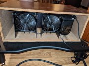
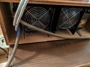
I have been working on the fan situation. I have settled on some new NMB ball bearing fans that run on 120AC. These fans run at a higher rpm than the old papsts fans that I was playing with. I wired those fans in series and just plug them into the same switched outlet that I use to turn on the amp.

Do you guys think it's safe to run these amps in wood cases with the fans like this? They are blowing onto the back of the amp, but there's not a good way for the hot air to exit. I was thinking of getting the hole saw out and cutting a couple 3 or 4" holes under the back plane of the amp. I don't really want to do that, but I'd rather the amps not overheat. The infinitys really give the amps a workout

PXL_20210525_010907324.jpg

PXL_20210525_172002802.NIGHT.jpg
 

mlucitt

Veteran and General Yakker
Joined
Jun 24, 2011
Messages
3,491
Location
Jacksonville, FL
#23
I would monitor the heatsink temperature. Do you have one of those IR temp guns? Also, the thermal cutout will shut off the amp if it gets too hot. Have you ever had a heat shutdown? The fan look like they are doing the job.
The amps actually need heat to operate the bias control circuitry, so I would not drill any holes.
 

rollcentre

New Around These Parts
Joined
Mar 22, 2021
Messages
48
#24
I would monitor the heatsink temperature. Do you have one of those IR temp guns? Also, the thermal cutout will shut off the amp if it gets too hot. Have you ever had a heat shutdown? The fan look like they are doing the job.
The amps actually need heat to operate the bias control circuitry, so I would not drill any holes.

Yeah, I sure do. It's somewhere lol. My past life as a mechanic I used them for a while until I got my hand-temp calibrated. Burn your hand hot (180F), uncomfortably hot (140F), hot (120F), warm (100F), and then room temp.

What temp does the thermal switch cut off?

I have not had the amp shut down yet because of the thermal cut out switch, but I haven had them running in wood cases yet.
 

wattsabundant

Chief Journeyman
Joined
Apr 26, 2011
Messages
933
Location
Central Ohio
#25
I did a post a year or so ago about a temperature controller for tower computers. The controller has thermocouples that read heatsink temperatures and adjusts the speed of 12 VDC fan motors. After I got the thing assembled and tested I found that my amps (in walnut cabinets) did not heat up before my ears complained. Two series wired 120 VAC fans moves plenty of air and is quieter
 

rollcentre

New Around These Parts
Joined
Mar 22, 2021
Messages
48
#27
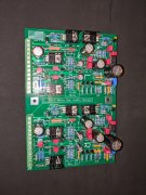
Alright gentlemen, I have populated the WO PL14-20G1 board for this amp. That was the fun part. Took me about a week and a half. Spent an hour or so a night on it. Triple checked my solder joints. (used 63/37 as recommended)

PXL_20210622_011329336.jpg


I have checked the 2N3 403 bias transistors on the back wall with my cheap Chinese multi function transistor tester. These are the results.

Right channel (the one that had bad outputs)
PXL_20210623_001041864.jpg

Here is the left channel-
PXL_20210623_002922174.jpg

Are there any additional tests that need to be performed on these bias transistors before I proceed? They seem to be good according to this test.
 

rollcentre

New Around These Parts
Joined
Mar 22, 2021
Messages
48
#30
Thanks, laatsch,

Don, I checked the relay, I didn't see any burns on the contacts. I think we're ok there.

Thinking back on it now, I should have just put the mini grippers on the ends of the wire going into the board. I tried to manipulate those bias transistors leads as little as possible.

I wired up a new input jacks, and I think I'll call it a night.

PXL_20210623_024638022.jpg
 

rollcentre

New Around These Parts
Joined
Mar 22, 2021
Messages
48
#32
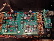
Ok gentlemen, I have it wired into the amp.

PXL_20210624_021049838.jpg

I attempted a shakedown run with a variac and DBT.

I was following the startup directions in the kit. I have only the bottom row of transistors installed. Everything seemed to come up, no burning smells, smoke, or popped fuses, etc. I took a DC offset measurement-

Left Channel- 8mV
Right- 0mV

The right channel fluctuated a bit for a min or so before settling in 0mV so, I think we're good.

In gonna call it a night!
 

Gepetto

Administrator
Staff member
Joined
May 15, 2011
Messages
14,018
Location
Sterling, MA
Tagline
Old 'Arn Enthusiast
#33
Ok gentlemen, I have it wired into the amp.

View attachment 51571

I attempted a shakedown run with a variac and DBT.

I was following the startup directions in the kit. I have only the bottom row of transistors installed. Everything seemed to come up, no burning smells, smoke, or popped fuses, etc. I took a DC offset measurement-

Left Channel- 8mV
Right- 0mV

The right channel fluctuated a bit for a min or so before settling in 0mV so, I think we're good.

In gonna call it a night!
You should have very close to zero on both channels...
 

George S.

Veteran and General Yakker
Joined
Feb 18, 2020
Messages
5,033
#34
Stop and make sure each wire at the phoenix connecters are tinned and insulation is stripped back sufficiently. You don't want insulation in the "clamp" contacts.
Would also be a good idea to heat and add a little solder where needed to each component on the top side of the board. *I solder each side*. Others have had intermittent issues solved after reflowing those joints. Joe puts a lot of copper into his boards, when I solder/build one I closely watch the board heat, flux flow, solder flow and penetrate through a magnifying headset called a MagniVisor. Some of those joints take more time and heat than others because of that extra copper.
 

rollcentre

New Around These Parts
Joined
Mar 22, 2021
Messages
48
#35
Thanks guys

I continued with the bring up instructions-

I got to the top row of transistors put them all in, did the start up procedure and it seemed to fail the DBT.

I got to around 30vac on the variac and the bulb would illuminate and stay lit, I slowly moved it up a bit and it just got brighter without dimming.

I started troubleshooting, removed the top row of transistors, and tried the start up procedure, and it passed the DBT this time.

I tested the top row transistors with my transistor tester and the appear to be good.

Seems the issue is isolated to the top row. Perhaps the stock PL backplane wiring on the top row? I will start checking there this evening.


Can I further isolate the problem by installing the two left channel top row transistors, and leave the two top right channel transistors out? The right channel was the one that initially had blown transistors..
 
Last edited:

George S.

Veteran and General Yakker
Joined
Feb 18, 2020
Messages
5,033
#36
You did ohm out all the components on the back wall with a good multimeter? I've read where sometimes the resistors crack or blow out on the backside where the damage is hard to see. Also, your positive those output cases or screws aren't grounding to the heat sink or chassis? They must "float" above ground. Easy to check with multimeter.
 

rollcentre

New Around These Parts
Joined
Mar 22, 2021
Messages
48
#37
You did ohm out all the components on the back wall with a good multimeter? I've read where sometimes the resistors crack or blow out on the backside where the damage is hard to see. Also, your positive those output cases or screws aren't grounding to the heat sink or chassis? They must "float" above ground. Easy to check with multimeter.
Hey George, I must have had something like that happen. I had checked all the back wall components a couple times and they seem good. I did again anyway.

I put the same 4 transistors back in the top row and it brought up fine this time.

I guess I did have a transistor hold down screw touching the back panel or something. This time unscrewed the control board to see from the backside, I just socketed the transistors with silpads under them without any screws to see if there was anything fishy with the sockets. It came up fine on the variac and DBT like this. I'll have to be more careful next time with the screws. The silpads looked fine too, but Ill replace them anyway.
 

George S.

Veteran and General Yakker
Joined
Feb 18, 2020
Messages
5,033
#38
Cool. Next time look and make sure the output socket is centered properly, and hold it tight against the back wall while you insert the screws and very lightly, just snug the output down. Then tighten evenly and lightly while closely watching the silpad edge. Once it begins to curl or wrinkle, stop! Your done tightening. I get my eyes as close as possible and use a Optivisor.
Also check for any burrs or roughness that may puncture the silpad. Sometimes I wonder if some used outputs may have a internal short or open that appears only when torqued thus stressing the case. Perhaps they've been over tightened in the past. I don't know. Have fun with your amp!
 

Gepetto

Administrator
Staff member
Joined
May 15, 2011
Messages
14,018
Location
Sterling, MA
Tagline
Old 'Arn Enthusiast
#39
Some of the original cheap sockets that PL used either crack on the inside sleeve due to age and heat or had gotten crushed during initial assembly at the plant exposing the possibility of the transistor hold down screw shorting to the chassis. The only way you can find those is to take the heatsink off.
 

rollcentre

New Around These Parts
Joined
Mar 22, 2021
Messages
48
#40
Alright guys, I'm back at it.

It is still failing the DBT, I have a continuity tester on my DMM, which helped me isolate some things.

It seems like I'm having trouble with involving
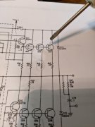
Q15 and Q17 (if I'm reading the schematic correctly) it's the output transistors 1st column from the power trans, 1st and 2nd rows down)
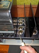
PXL_20210624_191640369.jpg

PXL_20210624_191738057.jpg


I have all of the transistors socketed and screwed down except for the screws in Q15 and Q17. The transistors are there, just no screws.

It will pass a DBT like this, but when I put screws in (even loosely) for Q15 and Q17 it will fail.

I have been testing it with my continuity setting on my DMM and I'll sometimes (not everytime) I get continuity between Q15 an Q17 and the chassis when the screws are in.

I'm looking at the schematic and trying to figure out what's going on. If D14 is open, or R43 or R45 is shorted it would be shorting the positive fused supply to ground when the screws are put in. Is this correct? I guess I should quadruple check those and use my DMM instead of the multi function tester.

If that isn't it, I'll pull the heatsink off and see if the socket is damaged and shorting to the chassis.

Can you guys think of anything else I can try?
 
Top