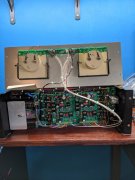
700b G1 Board Pad 1 and 2 Question - Signal Input

Vintage 700b

Chief Journeyman
Joined
Mar 13, 2019
Messages
828
Location
Wisconsin
Tagline
Fabricator
#1
Hello,
Working on a Full Comp, Dual Mono 700b. Power wiring is all done, now working on signal wiring. In building the Dual Mono version with the G1 board, do I not use the 1.750” copper plate when mounting the RCA jacks? This plate would work as a neutral bus of sorts as in the original amplifier set-up. I ask in trying to keep these neutral wires separate, not connecting the L/R channel input grounds together.
I have Pad 1 on the G1 board (driver circuit) on each channel connecting to the center tap on the attenuator pot/respective channel. The center tip of the RCA jack going to the center tap of the Direct/Normal switch, then out from LH side of the switch (looking from inside the amp – Right side lugs not used) to the far left attenuator pot lug on each respective channel.
Hopefully, this makes sense so far. I am confused now where the Pad 2 on the G1 board goes to? I thought naturally it would connect to the RH side of the attenuator pot (ground/neutral, but don’t I need to also bring a wire, or set of two wires (L/R) from the outside shells of the RCA jacks down into that attenuator pot lug (L/R) as well?
My description of the potentiometers above assumes that we are looking at the pots from the backside, lugs below. Left side to Tip of RCA Jack through Direct/Normal switch, Center to G1 Pad 1, and if this is correct so far, do I hook the Right potentiometer lug to the Pad 2 on the G 1 board? Is there then a second connection from RH of each Potentiometer (first going to Pad2) that runs to the respective RCA shell neutral? I have installed the correct resistors and caps between the Direct/ Normal switch and RCA plugs.
I hope I have explained this well enough. I may have missed something in the documentation?
Thank You
 

mlucitt

Veteran and General Yakker
Joined
Jun 24, 2011
Messages
3,497
Location
Jacksonville, FL
#4
You are on the right track. In order for the DC/Normal switch to work properly, the 220K Ohm resistors that are used to bleed the 1uF "Normal" cap must be connected to the low side of the input pair. I run RG-316 coax like this: center conductor from the DC/Normal switch "output" and outer braid from the RCA jack "outside" of the connector. Then the other end of the coax goes to the attenuator like this: center conductor to the "right" side of the pot and outer braid to the "left" of the attenuator. This assumes looking at the back of the faceplate and the pot terminals facing down. The second coax wire goes to the Control Board (as you described) and to the attenuator center terminal and the outer braid connects to the terminal with the outer braid from the input jacks. This way the inputs are grounded at only one place - on the Control Board.
 

mlucitt

Veteran and General Yakker
Joined
Jun 24, 2011
Messages
3,497
Location
Jacksonville, FL
#6
Belden is just one manufacturer, there are many others. As long as the wire is marked "M17/113-RG316" and "MIL-DTL-17H" or something similar, you know it meets the specification required by the military for use in aircraft and other critical applications. Be careful of the Chinese wire that is advertised as Mil-Spec, but is not marked every 12".
 

Vintage 700b

Chief Journeyman
Joined
Mar 13, 2019
Messages
828
Location
Wisconsin
Tagline
Fabricator
#7
You are on the right track. In order for the DC/Normal switch to work properly, the 220K Ohm resistors that are used to bleed the 1uF "Normal" cap must be connected to the low side of the input pair. I run RG-316 coax like this: center conductor from the DC/Normal switch "output" and outer braid from the RCA jack "outside" of the connector. Then the other end of the coax goes to the attenuator like this: center conductor to the "right" side of the pot and outer braid to the "left" of the attenuator. This assumes looking at the back of the faceplate and the pot terminals facing down. The second coax wire goes to the Control Board (as you described) and to the attenuator center terminal and the outer braid connects to the terminal with the outer braid from the input jacks. This way the inputs are grounded at only one place - on the Control Board.
I think I have it, but I need some clarification on the “second coax wire” that you mention. It only runs from the potentiometer to the G1 board? Center conductor from center potentiometer lug to Pad 1 on the driver board, and the outer braid from that second coax goes from left lug of potentiometer to Pad 2? (Lugs pointing down)
Both outer braids then connect to the left of the attenuator?
It appears that I had my Left and Rights mixed up coming out of the potentiometers.
Thank You
 

mlucitt

Veteran and General Yakker
Joined
Jun 24, 2011
Messages
3,497
Location
Jacksonville, FL
#9
Yes, you need two wires in the Phase Linear amps that have attenuators, just like they did it. Mark's excellent video above tells all.
I have done the wiring the wrong way around. And thank goodness my test signal was low! I wired the attenuators backwards. Always the wiper (center terminal) goes to the amplifier (Control Board).
If you want a wiring sanity check - who doesn't - ground your meter and put the red lead on the wiper. With the attenuators turned down (CCW) you should be reading very close to ground potential. With the attenuators turned up (CW) the reading should be infinity if nothing is connected to the input jacks.
 

Vintage 700b

Chief Journeyman
Joined
Mar 13, 2019
Messages
828
Location
Wisconsin
Tagline
Fabricator
#10
Perfect, I needed a wiring sanity check with this! Thank you for clarifying. I will get my meter on it now.
Was what I asked about that second coax correct? Going from the center lug of the potentiometer to Pad 1 on the driver board (G1) and the outer braid of the coax going from potentiometer ground/neutral and Pad 2 on the G1 board?
I do have some M27500-20SD2T23 wire (twisted pair cable) is that acceptable, or should I order the M17/113-RG316 ?
Thanks again,
 

MarkWComer

Veteran and General Yakker
Joined
Nov 1, 2014
Messages
3,514
Location
Gaston, SC
Tagline
Victim of the record bug since age five
#12
As long as the wire is marked "M17/113-RG316" and "MIL-DTL-17H" or something similar, you know it meets the specification required by the military for use in aircraft and other critical applications.
I do have some M27500-20SD2T23 wire (twisted pair cable) is that acceptable, or should I order the M17/113-RG316 ?
Thanks again,
Yeh, you can use the twisted pair, but nothing beats the nice mil-spec coax. PL used a two-conductor with shield cable, I never liked that idea, opportunity for noise.
 

Vintage 700b

Chief Journeyman
Joined
Mar 13, 2019
Messages
828
Location
Wisconsin
Tagline
Fabricator
#13
Hello Mark,
Thank You for posting your video, very well done. I had written down the exact routing, and my DVM testing concurred with both my diagram and your video. I am still not sure what connects to Pad 2 on the driver board. It would seem that the center wire on coax from the center lug of the potentiometer connects to Pad 1, and the "neutral" wire from that same piece of coax runs from potentiometer RH lug (has two 'Neutral" wires on it) to Pad 2.
The M27500-20SD2T23 wire is Military Spec-Teflon coated 600v rated 20 gage wire. I would weave these lines that are already twisted, one pair for Left Channel, and the other for Right Channel for noise . They would then be woven together quite well. Just wondering since I have that wire, and no 2 conductor M17/113-RG316.
The other thing that I had asked, was to use the copper bus under the RCA jacks for Dual Mono (Full Comp) or run separate L/R grounds through the driver boards only. (Which is how I was going to do it) George S. above commented No Copper, but I see you used it in your video. Thoughts on that?
Thank You all.....if I can just get Pad 2 nailed down.
 

George S.

Veteran and General Yakker
Joined
Feb 18, 2020
Messages
5,036
#15
Joe shows the copper plate being used in the schematic. I thought that was to be left out, resolving any potential ground loops between the two RCA jacks. Thoughts?
 

Vintage 700b

Chief Journeyman
Joined
Mar 13, 2019
Messages
828
Location
Wisconsin
Tagline
Fabricator
#18
Hello,
Thanks again for all of the help. I dug deep and found enough 2 conductor M17/113-RG316 18 gauge wire to wire this up. Not an inch to spare but it should work nicely.
Thank you all!
 

George S.

Veteran and General Yakker
Joined
Feb 18, 2020
Messages
5,036
#19
Separate at the copper plate area if you care to. It will do no harm either way.
Joe, got it, you had me worried for a short while. I remember when the "dual mono" boards came out that several builders were keeping the two channels separate as much as possible, not sharing the floating ground at the RCAs.
Are there any any just perceptible advantages or disadvantages at all when using the plate? Thinking building may be easier with the plate rather than those slip on grounding tab washers. Could wire the RCAs and plate right on the bench and drop it into the chassis.
 

George S.

Veteran and General Yakker
Joined
Feb 18, 2020
Messages
5,036
#20
Looking at some photos of the PL "pro" Clair Bros and Audio Analysts amps with 1/4" jacks in place of the RCAs. Hard to tell, but looks like no plate was used and perhaps the jack is grounded directly to the chassis.
 
Top