Vintage 700b
Chief Journeyman
Hello,
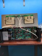
Working on a Full Comp, Dual Mono 700b. Power wiring is all done, now working on signal wiring. In building the Dual Mono version with the G1 board, do I not use the 1.750” copper plate when mounting the RCA jacks? This plate would work as a neutral bus of sorts as in the original amplifier set-up. I ask in trying to keep these neutral wires separate, not connecting the L/R channel input grounds together.
I have Pad 1 on the G1 board (driver circuit) on each channel connecting to the center tap on the attenuator pot/respective channel. The center tip of the RCA jack going to the center tap of the Direct/Normal switch, then out from LH side of the switch (looking from inside the amp – Right side lugs not used) to the far left attenuator pot lug on each respective channel.
Hopefully, this makes sense so far. I am confused now where the Pad 2 on the G1 board goes to? I thought naturally it would connect to the RH side of the attenuator pot (ground/neutral, but don’t I need to also bring a wire, or set of two wires (L/R) from the outside shells of the RCA jacks down into that attenuator pot lug (L/R) as well?
My description of the potentiometers above assumes that we are looking at the pots from the backside, lugs below. Left side to Tip of RCA Jack through Direct/Normal switch, Center to G1 Pad 1, and if this is correct so far, do I hook the Right potentiometer lug to the Pad 2 on the G 1 board? Is there then a second connection from RH of each Potentiometer (first going to Pad2) that runs to the respective RCA shell neutral? I have installed the correct resistors and caps between the Direct/ Normal switch and RCA plugs.
I hope I have explained this well enough. I may have missed something in the documentation?
Thank You