I blew out a couple output transistors on my PL400, what next?

rollcentre

New Around These Parts
Joined
Mar 22, 2021
Messages
48
#1
Well, there you have it lol.
I have two PL400s running a pair of Infinity RS-2.5 speakers. I have them biamped vertically. I was playing some good ol rock music today at fairly decent levels when the right amp's DC relay tripped .

I have both of these amps recapped (including the bulk caps) all new mj21196G except for one RCA410 per channel. The control boards have all original silicon and resistors. I also have Don"s DC relay boards installed

I went about troubleshooting, passed the DBT, idle current seemed normal if not a little lower than usual. I brought it up on the variac but the DC relay wouldnt energize. I measured the wire connectors on the board and found that the DC offset was still in spec 37mV, 25mV, but the pin J3-1 (DC power in) was at 0 volts instead of 70-80vdc. So I followed that down and found that this diode was open. It's showing as a resistor.
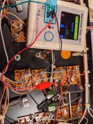
PXL_20210519_004307434.jpg

Digging a little deeper, I pulled all the output transistors on that channel and found two shorted with the same tester pictured above. That's just where I left off for the night, there very well could be more.

I don't think the amp latched up because of the normal seeming DC offset. I'm still trying to figure out the chain of events that led up to this failure

I know these are tough speakers to drive, but I've been monitoring the heatsink temps pretty closely for weeks, and they didn't get any warmer than the transformers at the levels I was playing. I was just "throttling" them for the time being since I didn't have fans on them.

However, the amp that busted I had just installed a pair of muffin fans between the heatsink fins for extra precaution. Could that have something to do with it? If the bias transistor was tracking cooler than the outputs or something... The fans are blowing right on the outputs. I have two 120v fans wired in series to slow them down quite a bit.

The second the relay tripped I jumped up and cut the power to the amp. I felt the right output heatsink and it was warmer than usual, and I had just powered up the amps a couple mins earlier. Heatsink was much too warm for that.

I'm still a bit of a newb. I know I could wopl it and get much better reliability, but I think that's still a little over my head. I feel like if I could learn a little about what caused a failure like this, that would help me understand a little more how everything works.

Thanks!

Keith
 
Last edited:

wattsabundant

Chief Journeyman
Joined
Apr 26, 2011
Messages
842
Location
Central Ohio
#2
You have a blown fuse which is why the dim bulb test was successful. There wasn't any DC to the outputs or the relay board. It's not likely the diode failed. You were reading the shorted transistor. It's rare that 2 outputs failed in the same bank/column. What likely happened is one shorted in each bank of that channel.

Attached is the 400 manual. Page 20 tells how to test the outputs in circuit. There is also information on how to test the rest of the transistors on the board. I have one of those transistor testers. For testing transistors in the amp a digital voltmeter is preferred.

Broken leads on the bias transistor can cause the outputs to go full on and the amp wouldn't necessarily be hot.

Summary: read the entire troubleshooting section, if not the entire manual. It's worth the time to do it. Check all transistors and diodes on the driver board, in circuit as well as the outputs. Compare the good channel readings to the failed channel. Check for broken wires from the driver board to the outputs. Do not buy a full kit of replacement parts off EBAY.
 

Attachments

Gibsonian

Chief Journeyman
Joined
Aug 3, 2011
Messages
777
#3
Not sure the root cause, but for me the reliability with the old boards was not good, but others have run em for years without issue, i.e. Don Imlay. A new main board does wonders ime for reliablity, but maybe some root cause for issues was in my board that was never properly fixed. I'm just a parts changer, don't know alot more than that. Good luck in your investigation!
 

rollcentre

New Around These Parts
Joined
Mar 22, 2021
Messages
48
#5
You have a blown fuse which is why the dim bulb test was successful. There wasn't any DC to the outputs or the relay board. It's not likely the diode failed. You were reading the shorted transistor. It's rare that 2 outputs failed in the same bank/column. What likely happened is one shorted in each bank of that channel.

Attached is the 400 manual. Page 20 tells how to test the outputs in circuit. There is also information on how to test the rest of the transistors on the board. I have one of those transistor testers. For testing transistors in the amp a digital voltmeter is preferred.

Broken leads on the bias transistor can cause the outputs to go full on and the amp wouldn't necessarily be hot.

Summary: read the entire troubleshooting section, if not the entire manual. It's worth the time to do it. Check all transistors and diodes on the driver board, in circuit as well as the outputs. Compare the good channel readings to the failed channel. Check for broken wires from the driver board to the outputs. Do not buy a full kit of replacement parts off EBAY.
You're exactly right.

I actually forgot about those fuses, but I just checked. Both rail fuses were open. The fuse filaments completely blasted away.

There was a blown transistor on each column on the right channel.

I suppose that since both rail fuses blew, I have some bad transistors on the left channel as well.
 
Last edited:

rollcentre

New Around These Parts
Joined
Mar 22, 2021
Messages
48
#6
Don't the 2.5's have some wicked impedance dips?
Yeah they do. They are 4 ohm nominal, but can dip down into the 2's. They have the dual coil Watkins woofers with the huge capacitors in the XOs. I have a suspicion that the quasi ribbon mids and tweeters are harder to drive than the dual coil woofer.

I'm in a smallish room and don't have to push them all that hard. Most of the time the meters barely twitch and that's a good listening level for me.

I love these speakers I just hope I can continue to run my PLs with them because they sound so good with them.
 

laatsch55

Administrator,
Staff member
Joined
Jan 14, 2011
Messages
74,124
Location
Gillette, Wyo.
Tagline
Halfbiass...Electron Herder and Backass Woof
#7
Had a friend in Az that had a pair of 2.5's that he ran with a pl 400 and 300. He had no problems with em...he kept em cool..
You blew a plus and minus rail fuse, the problem could be isolated to one channel. The plus is for both channels as is the minus...
 

wattsabundant

Chief Journeyman
Joined
Apr 26, 2011
Messages
842
Location
Central Ohio
#9
The typical failure is one output transistor, say the positive rail, shorts. That places the full 160VDC power supply across the negative outputs. The weakest one fails. It's a dead short from plus to minus. The fuses turn black because they arc. They're not rated to clear that high of DC.

When the amp is operational again, be sure to check the relay contacts.
 
Last edited:

wattsabundant

Chief Journeyman
Joined
Apr 26, 2011
Messages
842
Location
Central Ohio
#10
Yeah they do. They are 4 ohm nominal, but can dip down into the 2's. They have the dual coil Watkins woofers with the huge capacitors in the XOs. I have a suspicion that the quasi ribbon mids and tweeters are harder to drive than the dual coil woofer.

I'm in a smallish room and don't have to push them all that hard. Most of the time the meters barely twitch and that's a good listening level for me.

I love these speakers I just hope I can continue to run my PLs with them because they sound so good with them.
It's entirely possible that the front end transistors (Q1-4) are intermittent. That could cause DC offset that cascades to outputs. There are lots of other age related possibilities.
 

rollcentre

New Around These Parts
Joined
Mar 22, 2021
Messages
48
#11
Thanks guys. I just emailed Joe yesterday right before it blew. I was going to get a couple LED boards for the amps because I was so pleased with how they were performing. I emailed him back today to add a couple control boards- the new dual mono boards with phoenix connectors.

Gibsonian, I hear ya there, I'm primarily a parts swapper, and it has got me by for the most part. When I picked up these PL amps I started picking up a few tools and actually have a benchtop to work and diagnose things a little better. I think I may be able to handle doing the control board, especially with the help of you fellas.
 

rollcentre

New Around These Parts
Joined
Mar 22, 2021
Messages
48
#13
Hey Mark, actually the outputs were all MJ21196Gs. I had 2 RCA410 transistors on the bottom row (2nd and 4th column) I think they were referred to as the output drivers... thankfully those are still good because they seem hard to find.

I am gonna go ahead and get the parts from Joe to start wopling. That was pretty much the plan in the first place.

I have subbed in my old SAE mark 3 amp with a pair of JBL 4311s for the time being. I think that ought to hold me over.
 

mlucitt

Veteran and General Yakker
Joined
Jun 24, 2011
Messages
3,339
Location
Jacksonville, FL
#14
I missed where you stated those were MJ21196 transistors. They can take up to 30A momentarily, something serious caused them to short. I'm thinking a latch-up on the control board that then caused the DCP to save your speakers and the rail voltage had no where to go. The transistors will go before the fuses in cases like this. You turn the amp off, and turn it back on, and the latch-up condition is gone; it's weird.
You are wise to go with the WOA Control Boards, no more latch-ups, ever.
 

wattsabundant

Chief Journeyman
Joined
Apr 26, 2011
Messages
842
Location
Central Ohio
#15
With all due respect to Mark, I don't like the latch up theory. I've personally never seen it. That doesn't mean it can't happen, I just haven't seen it. I have seen marginal front end transistors that would ocassionally result in full DC on the output at start up. Sometimes the amp would start up ok. My understanding is this failure occured during operation. I believe latchup only ocurs at turn on. Correct me if I'm wrong.

I've seen lots of rock and roll PA 400's with failed outputs. Sometimes one fails in plus or minus leg. Sometimes one fails in both positive and negative legs. Many times replaceing the blown ouputs fixed it. The exception is when the guitar player, in deperation, wraps foil around the fuse. That results in fire. I have seen that.

I attached page 4 of the 21196 data sheet. The short story is that the outputs can only tolerate really high currents when used as a switch. In an amp they run linear (like a variable resistor) and have a much lower current rating at high voltages.

I've seen posts here knocking the MJ150214's. The safe operating area of the 15024 is very close to the 211296's. There is a reason a lot of mfr's used them. Most used 4, 5, or eve 6 per leg in a 200 watt amp. That dramatically improves the safe operating area and increases reliability.
 

Attachments

rollcentre

New Around These Parts
Joined
Mar 22, 2021
Messages
48
#16
My understanding is this failure occured during operation. I believe latchup only ocurs at turn on. Correct me if I'm wrong.
Correct. The amp was powered up for about 5mins, music playing at decent levels when it popped.

I had a pair of diodes paralleled with opposing bias across the c6 caps , I think that was to prevent the amp from latching up at start up. It was a suggestion, that I think you gave me over on AK.
 

mlucitt

Veteran and General Yakker
Joined
Jun 24, 2011
Messages
3,339
Location
Jacksonville, FL
#17
I had 2 RCA410 transistors on the bottom row (2nd and 4th column)
Roll, what did you have at the bottom of column 1 and 3?
Don doesn't like my theory, but it is only a theory. And he says he has seen many failed outputs in R&R amps, but those were probably not MJ21196 outputs. The MJ21196 transistors are strong, I have never seen one fail in an operating amp. Something like a power spike or an inadvertent (not anything anyone did) rapid power off and back on sequence might be the culprit. The blown fuses are a good indication that a short circuit to ground occurred in the rail supplies and that short circuit was likely the output transistors that shorted to ground because they are connected to the rail supply voltage (+80V on the collectors and -80V on the emitters). The question is what caused those output transistors to short to ground?

"I suppose that since both rail fuses blew, I have some bad transistors on the left channel as well.
Not necessarily, the rails are positive and negative, not left and right in the PL400. The PL700 has four rail fuses for positive left and negative left as well as positive right and negative right.
When an output transistor hard shorts to ground (like when a screw falls into the amp) and gets across Q14 emitter and ground, that -80 volts at .1 Ohms creates 800 Amps until the negative fuse can blow. That much current will surge across to the opposite side to the emitter of Q13 and take it out before the positive fuse can blow. Likely you would have heard that "Pop" unless the music was really loud.
 

rollcentre

New Around These Parts
Joined
Mar 22, 2021
Messages
48
#18
Roll, what did you have at the bottom of column 1 and 3?
Don doesn't like my theory, but it is only a theory. And he says he has seen many failed outputs in R&R amps, but those were probably not MJ21196 outputs. The MJ21196 transistors are strong, I have never seen one fail in an operating amp. Something like a power spike or an inadvertent (not anything anyone did) rapid power off and back on sequence might be the culprit. The blown fuses are a good indication that a short circuit to ground occurred in the rail supplies and that short circuit was likely the output transistors that shorted to ground because they are connected to the rail supply voltage (+80V on the collectors and -80V on the emitters). The question is what caused those output transistors to short to ground?

"I suppose that since both rail fuses blew, I have some bad transistors on the left channel as well.
Not necessarily, the rails are positive and negative, not left and right in the PL400. The PL700 has four rail fuses for positive left and negative left as well as positive right and negative right.
When an output transistor hard shorts to ground (like when a screw falls into the amp) and gets across Q14 emitter and ground, that -80 volts at .1 Ohms creates 800 Amps until the negative fuse can blow. That much current will surge across to the opposite side to the emitter of Q13 and take it out before the positive fuse can blow. Likely you would have heard that "Pop" unless the music was really loud.
I should have clarified that the 410s are in the 2nd and 4th column from the transformer, the 1st and 3rd column has MJ21196G, I read a thread somewhere on here a while back...i think it was Joe that recommended the 410s be in that position for better stability, instead of using all MJ21196Gs.

I dont think I heard anything unusual from the amp. I did hear a slight pop, but I'm almost certain it was from the speakers..i think possibly from the DC protection relay contacts.
 

Gibsonian

Chief Journeyman
Joined
Aug 3, 2011
Messages
777
#19
Always blew my original board PL amps while cranking, and usually pushing it. Even with 21196's installed, and fans. Whatever goes on with the old main amp boards, didn't work for very long ime. Haven't blown one since converting to WOPL on two such amps, one quasi one full comp, except for that time I probed badly with multi meter and destroyed one, operator error!
 

wattsabundant

Chief Journeyman
Joined
Apr 26, 2011
Messages
842
Location
Central Ohio
#20
The quasi comp versions has a parallel path that likes to oscillate if the RCA 410's are not used in the negative column. I found out the hard way. Credit to Joe on that one.

Roll, when you replace the board, send me the old one. I'll do a failure analysis and try to determine if a board failure caused your amp to blow. When you install the new board pay particular attention to the bias transistor on the failed channel. All your work will be for naught if there is an issue there. I once had a 700B that I put all new outputs in and the bias transistor failed. Took out all of the new outputs in that channel.
 
Top