You are using an out of date browser. It may not display this or other websites correctly.
You should upgrade or use an alternative browser.
You should upgrade or use an alternative browser.
A non-PL quasi-comp output transistor question
- Thread starter 62vauxhall
- Start date
62vauxhall
Veteran and General Yakker
- Joined
- May 14, 2014
- Messages
- 2,365
- Location
- Southwest Kootenays BC
- Tagline
- No such things as bad days, just bad moments
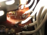
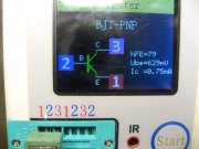
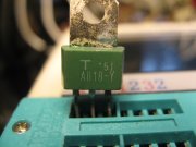
The 2SA818 data sheet I looked at was INCHANGE Semiconductor and it does say B-C-E. Yet that position on the PC board is marked differently....E-B-C. That was why I crossed the B & C legs of MJE15033 which is B-C-E.
Different pinout's from different makers of 2SA818 transistors?

And my "device" agrees with board's markings with the 2SA818 inserted....E-B-C.


Different pinout's from different makers of 2SA818 transistors?

And my "device" agrees with board's markings with the 2SA818 inserted....E-B-C.


Don't you just love Japanese transistors? No standards.
OK so by doing this you have confirmed something fishy going on at Q608 location. Next recommend that you put R627 end that you lifted back in and check results.
OK so by doing this you have confirmed something fishy going on at Q608 location. Next recommend that you put R627 end that you lifted back in and check results.
62vauxhall
Veteran and General Yakker
- Joined
- May 14, 2014
- Messages
- 2,365
- Location
- Southwest Kootenays BC
- Tagline
- No such things as bad days, just bad moments
R627 reconnected and voltage still positive and still at (+)52 volts.
That is a good sign. Now for the last reversal, reconnecting the collector of Q605 again and seeing what you get.R627 reconnected and voltage still positive and still at (+)52 volts.
And fingers crossed that it being put in backwards did not mortally wound it...
62vauxhall
Veteran and General Yakker
- Joined
- May 14, 2014
- Messages
- 2,365
- Location
- Southwest Kootenays BC
- Tagline
- No such things as bad days, just bad moments
Reconnecting Q605's collector caused voltage to change from (+)51 volts to approximately (-)0.8 millivolts. And the amp did not go into protection.
Bingo, you found your culprit. A wounded transistor from the one being put in backwards in the Q605 location that you discovered.Reconnecting Q605's collector caused voltage to change from (+)51 volts to approximately (-)0.8 millivolts. And the amp did not go into protection.
You probably should replace Q605 when you can since it saw abnormal duty when it was in backwards.
Carry on. Time for 2 outputs with the DBT
62vauxhall
Veteran and General Yakker
- Joined
- May 14, 2014
- Messages
- 2,365
- Location
- Southwest Kootenays BC
- Tagline
- No such things as bad days, just bad moments
I'd be more confident if Q605 was replaced, it's a 2SC1628. As is it's partner, Q606.
I mentioned earlier on page 4 - post #80 (jeez this has run long), that I have KSC3503 which are supposed to sub for 2SC1628. Would you agree....put KSC3503's at Q505 & Q606?
Re the outputs: All have been removed from both channels. When I install two, I'll do so two on each channel. And at this stage, I should be using the new ones, not what good ones are left of the old batch?
EDIT: DBT has been in use all along. Will continue doing so while installing the outputs.
I'd be more confident if Q605 was replaced, it's a 2SC1628. As is it's partner, Q606.
I mentioned earlier on page 4 - post #80 (jeez this has run long), that I have KSC3503 which are supposed to sub for 2SC1628. Would you agree....put KSC3503's at Q505 & Q606?
Re the outputs: All have been removed from both channels. When I install two, I'll do so two on each channel. And at this stage, I should be using the new ones, not what good ones are left of the old batch?
EDIT: DBT has been in use all along. Will continue doing so while installing the outputs.
You will have to swizzle the pins, the 2SC1628 is E-B-C vs KSC3503 being E-C-B
It is a better transistor than the original, an MPSA42 would be better but you probably don't have. Just do the channel that was misbehaving, the one you are working on. Use the old transistors for outputs if they are still good.
Once you get the dog channel remedied, then you can populate the other channel. Did you put an MJE15033 in the Q603 location as well? I think you did.
62vauxhall
Veteran and General Yakker
- Joined
- May 14, 2014
- Messages
- 2,365
- Location
- Southwest Kootenays BC
- Tagline
- No such things as bad days, just bad moments
Many thanks Joe, I am actually beginning to imagine and end to this thing.
Yes, an MJE15033 is at Q603. And KCS3503's are at Q605 & Q606. Voltages are within a few millivolts of 0 volts and protection is not engaging.
It must wait until tomorrow but I'll do as you say re the outputs and installl originals in only the left, as you say "dog", channel for now. Two at a time with DBT. I'll not install any outputs in the working right channel.
I noticed that bias still remains non-adjustable at 0.0 volts with no output transistors in place. Presumably that will not be so when some are installed?
If/when the left channel is restored to functionality with original outputs in place, I'm assuming the next step would be to proceed putting in the new outputs? Again, two at a time in both channels with DBT and final bias adjust will be without DBT?
Many thanks Joe, I am actually beginning to imagine and end to this thing.
Yes, an MJE15033 is at Q603. And KCS3503's are at Q605 & Q606. Voltages are within a few millivolts of 0 volts and protection is not engaging.
It must wait until tomorrow but I'll do as you say re the outputs and installl originals in only the left, as you say "dog", channel for now. Two at a time with DBT. I'll not install any outputs in the working right channel.
I noticed that bias still remains non-adjustable at 0.0 volts with no output transistors in place. Presumably that will not be so when some are installed?
If/when the left channel is restored to functionality with original outputs in place, I'm assuming the next step would be to proceed putting in the new outputs? Again, two at a time in both channels with DBT and final bias adjust will be without DBT?
Correct, bias will not be achievable without outputs in place. Perform everything with DBT so you do not blow anything up in the process.
62vauxhall
Veteran and General Yakker
- Joined
- May 14, 2014
- Messages
- 2,365
- Location
- Southwest Kootenays BC
- Tagline
- No such things as bad days, just bad moments
So far, so good. Thanks a million Joe.
Installed the old outputs two at a time in the left channel as directed. DBT dimmed after each pair inserted, bias is now adjustable and I can play a CD through a speaker.
The right channel was OK a couple of months ago. Even if being over cautious, I planned to remove those four old outputs from the left channel and use them to bring up the right channel the same way.
If all is good, I'll put in the new MJ21194G's in both channels, again two at a time with DBT.
Should final bias adjustment be with no DBT or does it not matter?
The service manual says to set bias at 30mv which would be with the stock Toshiba 2SD426 outputs.
Will the new MJ21194G's need a different number?
Final bias setting should be without DBT
You should use the same bias number for the new transistors.
Good that you got rid of those 2SA818 devices. Those are pure junk.
You should use the same bias number for the new transistors.
Good that you got rid of those 2SA818 devices. Those are pure junk.
62vauxhall
Veteran and General Yakker
- Joined
- May 14, 2014
- Messages
- 2,365
- Location
- Southwest Kootenays BC
- Tagline
- No such things as bad days, just bad moments
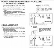
The new outputs are in and bias (no DBT) is now at 30mv as per service manual.
There is another adjustment in the manual referred to as DC Balance Adjust but to perform that, according to instructions, a VTVM is needed. I do not have one of those. A DMM does not seem useful. I guess it’s not capable of a stable zero volt reading.
I’ve only been inside a few amplifiers and have not encountered this adjustment before.
Is it critical?

I observed the heat sinks are warmer at idle than the output transistors themselves. I expected the transistors would be at least just as warm. A sign of good heat sinks?
Offset at speaker terminals are negatives (-)7mv & (-)15mv.
Tomorrow I’ll hook up speakers, a line & phono source.
There is another adjustment in the manual referred to as DC Balance Adjust but to perform that, according to instructions, a VTVM is needed. I do not have one of those. A DMM does not seem useful. I guess it’s not capable of a stable zero volt reading.
I’ve only been inside a few amplifiers and have not encountered this adjustment before.
Is it critical?

I observed the heat sinks are warmer at idle than the output transistors themselves. I expected the transistors would be at least just as warm. A sign of good heat sinks?
Offset at speaker terminals are negatives (-)7mv & (-)15mv.
Tomorrow I’ll hook up speakers, a line & phono source.
Last edited:
wattsabundant
Chief Journeyman
You have to be a fossil to know that a VTVM is a vacuum tube voltmeter which was replaced by most any DVM.
62vauxhall
Veteran and General Yakker
- Joined
- May 14, 2014
- Messages
- 2,365
- Location
- Southwest Kootenays BC
- Tagline
- No such things as bad days, just bad moments
You have to be a fossil to know that a VTVM is a vacuum tube voltmeter which was replaced by most any DVM.
Before I moved to the sticks, I was able to borrow a VTVM but don’t have that option anymore. Can’t remember why exactly I did borrow it other than to make the same adjustment, whatever it was, to a couple of 8 track recorders.
In this latest instance, the DMM’s display would not show a constant number. Granted the variance was a few millivolts but I imagine the needle of an analog VTVM would more or less stay in one spot.
mlucitt
Veteran and General Yakker
The analog meters were good if you needed to see the voltage increasing to your value or decreasing to your value. The DVM/DMMs just show flashing digits.
- Joined
- Jan 14, 2011
- Messages
- 75,795
- Location
- Gillette, Wyo.
- Tagline
- Halfbiass...Electron Herder and Backass Woof
Were you on DC range Gary?
The new outputs are in and bias (no DBT) is now at 30mv as per service manual.
There is another adjustment in the manual referred to as DC Balance Adjust but to perform that, according to instructions, a VTVM is needed. I do not have one of those. A DMM does not seem useful. I guess it’s not capable of a stable zero volt reading.
I’ve only been inside a few amplifiers and have not encountered this adjustment before.
Is it critical?
View attachment 47275
I observed the heat sinks are warmer at idle than the output transistors themselves. I expected the transistors would be at least just as warm. A sign of good heat sinks?
Offset at speaker terminals are negatives (-)7mv & (-)15mv.
Tomorrow I’ll hook up speakers, a line & phono source.
They are warmer but you can’t feel the area that they are warmer, on the die attach side between the base and emitter pins. The transistor cans are steel and don’t conduct heat like aluminum does
62vauxhall
Veteran and General Yakker
- Joined
- May 14, 2014
- Messages
- 2,365
- Location
- Southwest Kootenays BC
- Tagline
- No such things as bad days, just bad moments
Were you on DC range Gary?
Hi Lee. Yeah, DC range. I played a full CD then an album side and measured again. With and without speakers connected. Once done fiddling with the adjustment pots, both channels were rising and falling a millivolt or two above and below 0. So I'm calling that adjustment done.

