Northwinds
Veteran and General Yakker
- Joined
- Mar 18, 2013
- Messages
- 7,571
- Location
- Coventry, CT
- Tagline
- Fondler errrr... fan of all Nav's avatars
Now that is a groovy BABB 

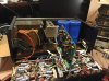
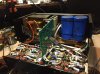
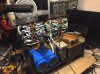
All the wiring is finished. All ready for the first power up through the DBT. If that goes as it should then I will load the drivers. Yes it is upside down. So tomorrow will be fun.
I guess the WhiteOak design doesn't use any ferric beads in the 700 so got to try it out.Ed and I were talking about the lack of ferrite beads on this build the other day Glen. It will be nice to know that little tidbit...
I guess the WhiteOak design doesn't use any ferric beads in the 700 so got to try it out.
Ed and I believe the fly back diodes are not required allthought most full comp designs I have looked at have them. Again we will see.
Why is that a bad idea Sir Joe??
Do not remove the flyback diodes, bad idea.
Ok they are going on tonight. Easy to doThey are there to prevent external inductive kick from exceeding the rail voltages and thereby exceeding the Vce of the output devices. It is not unusual to get many hundreds of volts inductive kickback if you develop an intermittent connection of your long wires to your speakers that the amp is pumping current into at the time. Most woofers in your speakers have an in line inductor in the crossover that add to the inductance of your speaker wire.
While in normal operation, these flyback diodes do nothing. But in the event of abnormal operation as described above, you will be glad they are in there.
PS: Don't cheap out, put them in...
Lee I have always questioned the location of these beads anyway. My simple mind thinks they should be on the base between the prediver and the rest of the outputs. Not in the middle of the string of outputsSince we started using the backplanes, I haven't tried to kludge a ferrite bead in there. Don't think you could. The only 700 stocker that I wired from scratch, I left out the beads because I was using Joe's board. Didn't have any problems, and I was using the 96's.....