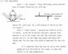
The way the technicians in the Phase Linear service department actually adjusted the bias on the amplifiers was by looking at the crossover notch (using a distortion analyzer, oscilloscope, signal generator, dummy load, etc.) at 1 watt @ 1KHz into an 8 ohm load and compromising (by means of the bias trimpot) between both states of the amplifier being HOT and COLD at 1W @ 1KHZ. NOTE: In order to create the HOT condition the amplifier is driven at 1/3rd power into a 4 ohm load in order to generate enough heat to create a HOT condition and then checked again at 1 watt at 1KHz. (I will call this a dynamic bias adjustment). This is done by sight and without measuring across the 10 ohm resistors. NOTE: In some cases the bias will go up when the amplifier is HOT and some cases it will go down.
After the dynamic bias adjustment has been made, I have found that the amplifiers are typically biased more towards 450mV when measured in an idle state (as is detailed in the service manuals). The 450mV may also be a bit higher due to the fact that many of the 10 ohm carbon composition resistors are now measuring higher (i.e. 11 ohms) as a result of the drift upwards in value over the years (as is common for carbon composition resistors).
The exception to this dynamic bias adjustment in the Phase Linear service department were fully complementary output amplifiers like the 300 series II and the PRO 700’s which exhibited very low distortion (due to a simple capacitor modification/relocation). As a result of this lower distortion the crossover notch is much smaller and is harder to see and therefore harder to adjust. The Phase Linear amplifier service manuals will state something like: “allow a sufficient warm up time†or “allow a 5 minute warm up period†before adjusting bias. The typical range of bias for Phase Linear amplifiers is approximately 300mv to 450mV. (NOTE: In most series 1 amp service manuals the upper end is listed around 400mV.) I call this type of bias adjustment a static bias adjustment. This is also done without the benefit of observing the crossover notch and utilizing the test equipment listed above. In the case of the 300 series II and PRO700's the bias was adjusted to approximately 385mV.
NOTE: I personally will not service any amplifier without observing the crossover notch. I use the test equipment noted above at a variety of frequencies and output levels. You never know what kinds of oscillations, noise, etc. you might encounter. Simple static bias adjustments will not reveal what is really going on inside your amplifier.
Hopefully all of this will all make sense. If not, please post your reply with your questions and I will do my best to answer.
By the way, there is a Carver M-400t amplifier service manual (page 48 I believe it is) which gives an approximate example of what the crossover notch should look like. The Phase Linear amps are slightly different. Someday I will post some pictures.
Ed