Zach's 700B Thread

Zach C.

Journeyman
Joined
Feb 12, 2013
Messages
384
Location
Southwest Indiana
Tagline
---
#21
Yes it does. It certainly can oscillate without the zoebel as well as it hooked up. Q4 is an MPSA 93. Still a good number and they make em every day. Q3 could be a TIS-93(now obsolete) or a 2N5087(current).
OK,I'll grab some form Mouser in the next couple of days.
Did you separate the hardwire ground from the RCA input ground plane from the speaker out grounds. When installing Don's board necessitates running a new ground wire from the board to the star ground point between the PS caps. Run a new ground wire from the input RCA ground plane to the the star ground point.
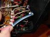
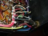
Note:All of the following is suspect- working from memory! I installed (then removed) Don's board as the instructions dictate. That called for one to tie all of the existing grounds together at the DC board, and run a fresh ground to the star. I have not, but can run a new ground directly from the RCA inputs to the star ground. I'm away from the unit right now, but my recollection is that a ground goes from the RCA to the Direct Coupling switch, and then to the ground on the Don's board. So, right now, I have that ground, the Driver Board ground, and the speaker grounds all tied together. This is the factory layout, but one Don thing commented on as being odd was that I have a ground wire which runs across the center of the outputs and back to the star. I have seen this in other PL's (400?) so maybe he meant that it was uncommon in a 700B? Not sure about that. I can't see a reason to have this ground, since it ties to the chassis twice in between the outputs, and once at (near?) the input RCA's, and creates the possibility of a ground loop, right? Confused. I think I saw an alternate ground schematic on here somewhere for a 400, but that should work. I'll try to post a pic or two of my amp tonight.

Do you have the problem with the Normal/DC coupling switch in either position.
I can't answer that for certain, but I'm fairly sure that I tried both and it was unchanged.

I'm thinking maybe I should look at a comprehensive overhaul of the grounding in this amp. As I understand it, the current layout is not "best practices" anyway.

How are you laying these out?

Thanks!

Zach
 

Zach C.

Journeyman
Joined
Feb 12, 2013
Messages
384
Location
Southwest Indiana
Tagline
---
#23
Note:All of the following is suspect- working from memory!
Well, I was right- that was wrong. Further reflection tells me that there are 4 grounds which tie together on Don's board, and the speaker grounds are off to the side.

Whoops.

It still sounds like I need to re-do the grounding strategy.

Zach
 

Zach C.

Journeyman
Joined
Feb 12, 2013
Messages
384
Location
Southwest Indiana
Tagline
---
#24
Zach, getting the Pl020 board up and stable is a good thing before putting in the WO board. If you have chassis issues that new board could take a hit. The single sided 020 is A LOT EASIER to replace components than the two sided WO board.
Agreed. I deal with double sided boards a bit at work- major PITA to fix sometimes. Worth it in this case, though.
 

Gepetto

Administrator
Staff member
Joined
May 15, 2011
Messages
13,575
Location
Sterling, MA
Tagline
Old 'Arn Enthusiast
#26
AC Wiring improvements in the PL700B

Hi Zach
Marks diagram has the single point ground covered.
This blog I wrote may help lead you in the right direction on the AC wiring improvments.

I recently rebuilt a PL700B for a friend, this BLOG is a result of that. It has been years since I rebuilt my own PL700Bs (before the age of internet BLOGS) so had forgotten most of what I rediscovered with this rebuild.
I always enjoy seeing the inside of an amp where all the wiring seems nicely organized and neatly laced with ty wraps. It looks great but when you peel back the covers, it is often counter to achieving the best signal integrity. Usually a couple of simple modifications make a huge difference in the noise floor an amp can achieve.
The primary rule is keep noise sources, especially AC noise sources away from amplifier inputs and input wiring, even if shielded. The amp circuit design has great power supply rejection ratio for defending noise signals from coming in the back door but has no defense against noise signals coming in the front door, after all, amps are designed to amplify these. If an input absolutely has to be near a noise source, keep any wire crossing at 90 degrees to the noise source and keep it to a single cross. The original lacing of the PL700B violated this rule in several areas.
The second rule is always use a single point ground. It can be vexing at times to get a single point ground scheme right but once you do it yields great benefits and usually looks the cleanest too. The original ground scheme used in the 700B violated this rule in several areas.
The 700B is somewhat unique in that the AC comes in on the right hand side of the amp (when looking from the front panel side), goes through a fuse and to a convenience outlet and then proceeds to run from right to left to go to the main power transformer. Likewise the rectified DC B+ and B- wires run from the left side of the amp to the fuses on the right hand side and then back to the left again to the application point on the back wall and the control board. This is hardly ideal and leads to many parallel runs of AC and DC.
With those 2 rules in mind, tackle the AC wiring in the 700B first. The best way to route the AC line in the 700B is to bring it from the fuseholder directly up to the left of the fuseholders and the convenience outlet, to the left of the output binding posts and the input selection switch and the input jacks but to the right of the last column of output transistors. Keep the AC wiring nested as close to the chassis metal wall as possible. At the top of the chassis, make a bend to the left and run the AC across the top of the chassis under the lip flange in the chassis. Get rid of the wire run to the two thermal switches that are mounted on the chassis back wall that run from left to right as well and re-route this to the top of the chassis as well. At each of the thermal switches, make a 90 degree bend straight down to the thermal switch and back up again to the top of the chassis. Tyrap these closely together to keep these needed AC runs away from the other wiring and transistors. Join the wire run that goes to the front panel switch over at the left hand transformer side of the chassis and run these to the front panel switch nested closely to the left wall of the chassis. Form these AC wires so that they do not come near the left channel volume pot or shielded wiring, it is very possible to do. I jacket these wires to keep them together and manageable. Unlace the 2 green low voltage AC wires that power the light board on the front panel and route them along with the AC line wiring discussed prior. These wires are long enough to route this way and it keeps them well away from any signal wiring. This rewiring should leave the bottom edge of the amp chassis devoid of any AC wiring. On the top edge of the chassis, lace only the AC wires together and lace the shielded input wires together and separate from the AC wiring runs. Push the AC wires into the upper inside bend of the chassis sheet metal, these should be the only wires in this area. Neaten up and re-lace the left to right DC voltages and ground wires that are now the only wires left in the bottom section of the chassis. Confirm that there is no AC present in any of the DC or signal wiring anymore.
 

mlucitt

Veteran and General Yakker
Joined
Jun 24, 2011
Messages
3,389
Location
Jacksonville, FL
#27
Joe posted the best response to the PL700 AC issue. Here is a picture of my first attempt to reduce the AC hum, I used a IEC shielded filter receptacle but have not yet routed the wires along the fold in the chassis wall. That was to be the next step.

Here are the before and after shots:

Mark
 

Attachments

Gepetto

Administrator
Staff member
Joined
May 15, 2011
Messages
13,575
Location
Sterling, MA
Tagline
Old 'Arn Enthusiast
#28
Here are some photos of the rebuild to helpfully work along with the narrative. You can see the basic routing of the AC along the top edge of the chassis and where I re-routed the bring out for the AC switch and the light board. Some photos of the revamped input switch as well to further reduce input noise.
DSCN0007.jpg DSCN0005.jpg DSCN0004.jpg DSCN0002.jpg
 

Gepetto

Administrator
Staff member
Joined
May 15, 2011
Messages
13,575
Location
Sterling, MA
Tagline
Old 'Arn Enthusiast
#29
Somewhat hard to see but there is an easy tie-off trick on the bias transistors to remove the stress on the leads. You can see it in the photo with the board flipped down if you look carefully. Should have taken a close up but missed that opportunity.

Those are fragile and will break when you are working on them so be careful to protect them.
 

laatsch55

Administrator,
Staff member
Joined
Jan 14, 2011
Messages
74,293
Location
Gillette, Wyo.
Tagline
Halfbiass...Electron Herder and Backass Woof
#31
Does relocating the AC mains in by the transformer have as great n effect as careful routing of the AC from the input section(the right)?? Seems like 90% of this could be avoided by kicking the thermodiscs to the outside on the heatsink and keeping the AC in by the transformer....
 

Zach C.

Journeyman
Joined
Feb 12, 2013
Messages
384
Location
Southwest Indiana
Tagline
---
#34
I put this together last year, it may be helpful. This is for the PL400, the PL700B is very similar.

Mark
Thanks! That's helpful for sure. It was your schematic that I was talking about, I just couldn't remember exactly where I saw it.

From you schematic, it looks like I should add 10 caps total to help quiet things.

4) .22uF Bridge
4) .33uF Low ESR DC Supply to Common
2) .47uF Across Supply Caps.

Can you recommend types for these? I'm getting ready to make a Mouser order, so if you're got Mouser #s, that would be even more super, but if not, I can work it out. I'm just not sure I know what type is best where. I could probably work that out too, of course, but if you already have...:D

Also, your schematic shows B+ to the DC protect board, is this correct? My DC board only takes AC? Are the 400's different here? confused.
Why is there a 2.2r in the ground for the two terminal strips between the outputs?

Thanks,

Zach
 
Last edited:

Zach C.

Journeyman
Joined
Feb 12, 2013
Messages
384
Location
Southwest Indiana
Tagline
---
#35
So, it sounds like I have some background work to do before we proceed.

This is my "to do" list at this point.

Re-route A/C
Re-wire ground scheme
Add bypass caps
Fix Q4 (that I broke)
Order replacements for all small signal transistors (cause they're cheap)
Install better caps/ resistors at coupling switch
Buy/ Install Phoenix Terminals on WO (for later, when the amp is running)
Replace melted C14R on WO Board

After that, I can start taking measurements that laatsch55 was asking for in trying to find the real problem. Maybe, just maybe the ground re-wire might help.

Should I add 4 MJ15024 to my order to use as drivers, since laatsch55 had concerns about the gain on the SJ2741 that are in there now? I assume that Don meant he was using these for all T03 devices in the text I copied from another post, and I could switch to these everywhere if it proves necessary later.

If anybody has any corrections, amplifications, and/ or, additional "background" steps I should carry out before really digging in (esp. wrt buying parts), please let me know. I'd like to think that I'm not totally lost here, but I sure don't think I've got a handle on all of this either. I'm wide open to your wisdom!

I'll tear into the wiring this weekend, and order on Monday, most likely.

Thanks again to all for the help!

Zach
 

Gepetto

Administrator
Staff member
Joined
May 15, 2011
Messages
13,575
Location
Sterling, MA
Tagline
Old 'Arn Enthusiast
#37
Zach
The shielded input wires are tied to themselves and NOTHING else. They are stiff enough to be self supporting. Separate these from AC and DC power wiring. The amp has a Power Supply Rejection Ratio that is very good and it will reject noise coming in on the power supply rails. However it will not reject noise coming in through the input wires as the amps purpose is to amplify these.

The photo was provided in the case you show to illustrate how to wire the 2 AC thermal cutout switches from the top edge of the amp rather than the original single wire AC run right through the center of the amp chassis.
Thermal_Sensor_Closeup.JPG

Couple other items:

Melted C14R??

DO NOT use MJ15024 or MJ21196 for the predrivers. Unless they are confirmed BAD, use the SJ2741 or RCA410 predrivers that are stock with the amp. Use of MJ15024 in the predriver location on the lower half of the amp output can lead to spurious oscillation (you can hear it too). A local feedback loop is formed between Q7, Q12 and Q14, 16, 18, 20, 22 on the lower half of the output bridge. If any of the SJ2741s is confirmed bad, get a replacement, they are available.
 

Gepetto

Administrator
Staff member
Joined
May 15, 2011
Messages
13,575
Location
Sterling, MA
Tagline
Old 'Arn Enthusiast
#38
Do you want me to attach the original hi rez photos so you can zoom in with some photo software you might have?
 

Gepetto

Administrator
Staff member
Joined
May 15, 2011
Messages
13,575
Location
Sterling, MA
Tagline
Old 'Arn Enthusiast
#39
One other thing, as Colombo always said:
if you solder the wires into the WO board (rather than using the Phoenix Contact connectors), do so on the backside of the board as shown in the photos I provided. Some installations I have seen bring them in from the front which adds a lot of stress to the wire joint as the wires have to do a 180 and secondly, it looks much neater and professional to bring them in from the back. After soldering, deflux any rosin flux using a small brush and isopropyl alcohol (put a couple layers of paper towels below the board edge when you do this)
 

Gepetto

Administrator
Staff member
Joined
May 15, 2011
Messages
13,575
Location
Sterling, MA
Tagline
Old 'Arn Enthusiast
#40
Zach
Here is how to stress relieve the 2N3403 bias transistor mounting. Shown in photo below. Orient the strap such that the leads exit straight up and carefully tie wrap the output bundle to the bus wire that runs north south between the TO-3 output sockets. There is one of these bus wires that usually has a glass braided sleeving on it. I tie off to that. No need to overtighten the tie wrap. Ensure the nut that holds the bias transistor strap is tight or you will not get a good thermal path between the chassis and the bias sense transistor (essential).

Bias_Transistor_Closeup.JPG
 
Top