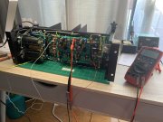
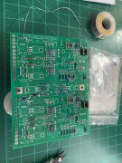
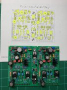
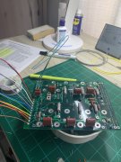
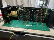
Everything is proceeding smoothly and then an "Ah Shit". First, I tested the power supply - both B+ & B-, without connecting either the WOPL PL400 backplane or the WOPL PL14-20 control board. It tested fine - about +/- 82 vdc. Then I connected power to both the backplane and the control board and power up through a Dim bulb tester. Just the bottom row of output transistors (drivers) were installed. 1 amp fuses installed. Everything came up normally - right and left output voltages were 0.0 mVDC & 0.4 mVDC respectively. Both B+ & B- were around 80vdc. Checked +15 on the control board. It's okay. Checked -15 on the control board - it's okay. And then, as I was removing the probe from the -15vdc test point on the control board, the micro-clip touched the heat sink of Q2 and I saw a little tiny arc. -15 died instantly. The heat sink is at the same potential as the collector of Q2, which is about -78vdc. Troubleshooting, I found a blown pico fuse on the right channel back plane. I replaced this (fortunately the kit provided extras), but the damage was done.
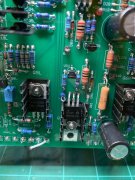
I wasn't sure what else was killed, but suspected the voltage regulator VR2, a TL431, the zener diode, D81, and both Op Amps, U1L & U1R. So I removed and replaced all. That fixed it.
In order to prevent this from happening again, I put a bit of heat shrink on the heat sink tine that is close to this test point. But now I check the -15 from pin 4 of the op amps. This is at the top of the board and is easy to get to.
I've now added all the backplane transistors and have set the bias. Everything is good. Life is good - for the moment.
A couple of notes:
1) The clearance between the top mounting bolt and nut (which is connected to the chassis) of the PL14-20 board and the heat sink of Q1 is tight. The heat sink has +80vdc on it. Ensure there is adequate clearance. This applies to the bottom mount as well.
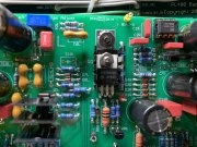
2) There is an error is the Assembly Notes for PL400 BackPlane Rev C PCB document, step 31, where it instructs to install only the pre-drivers in locations XQ11 & XQ12. Must be a carry-over from the PL700 as there are no XQ11 & XQ12s. Should be XQ7 & XQ8.
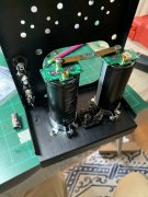
3) The light kit - it would be nice if the instructions labeled what goes to PAD1 through PAD5. And that matched the photos in the instruction. (The instructions discuss PAD1, PAD2, PAD3, PAD8 and PAD9). The instructions must show an earlier version of the board and silk screen. But in the end, it was easy enough to figure out.
4) Can't say enough good things about the kits. Everything is first rate. Often extra parts - nuts, screws, diodes, sil-pads, pico fuses - are included. Boy, does this help.
