
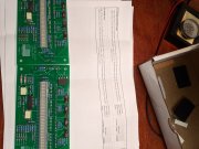
Built up a set of meters today and need help translating engineer speak to hobbyist. The wiring looks straight forward but want to make sure I understand the calibration for a 400.
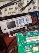
Calibrate one channel at a time. Attach a True RMS voltmeter to the output. Make sure the amps attenuator is set for highest output.
Set my signal generator for 500Hz sine wave at 3 volts amplitude. Connect the signal generator to the channel I'm calibrating and turn on the amp while watching the volt meter.
Slowly bring the sine wave amplitude up until I see 40Vrms at channel output, which should be appx 3.198298 volts peak to peak amplitude on the signal generator.
At this point adj the boards 10 turn pot to just illuminate the 31st segment.
Is this correct? Want to possibly get these installed next weekend.
Attachments
-
 2.1 MB Views: 13
 -
 1.9 MB Views: 13
Last edited: